Ford Mustang (1999-2004) Service Manual: Installation
1. NOTE: Inspect the spring insulators for wear or damage. Install new spring insulators if necessary.
Make sure the spring insulators are correctly installed on the springs.
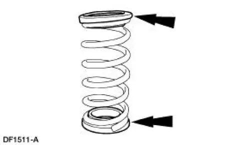
2. Install the springs.
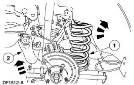
1. Position the springs.
2. Raise the subframe using the special tool 014-00765.
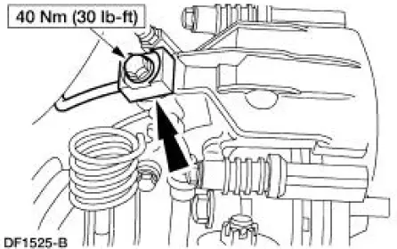
3. Install new bolts.
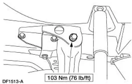
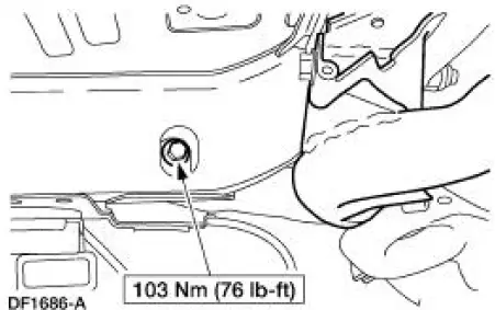
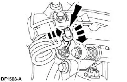
4. Remove and discard the subframe front bolts.
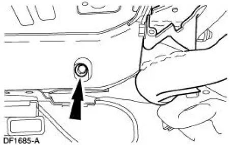
5. Install new bolts and nuts. Tighten the bolts.
6. Remove the special tool 014-00765.
7. Support the lower suspension arm and bushings with jack stands.
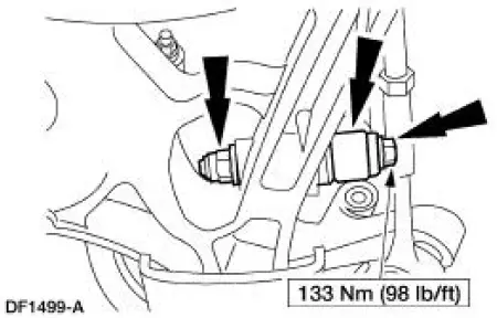
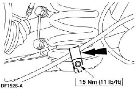
8. CAUTION: Make sure the hardened washer is installed between the lower suspension arm and bushing and the shock absorber. Failure to do so can result in damage and failure of the lower suspension arm and bushing.
Connect the shock absorbers to the lower suspension arm and bushing and install new bolts and nuts.
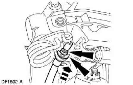
9. Clip the ABS sensor wires to the subframe.
10. Install the ABS sensors and the bolts.
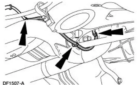
11. Connect the rear brake lines and install the bolts.
12. Connect the parking brake cable and conduits to the lower suspension arm and bushings and install the bolts.
13. Connect the parking brake cable and conduits to the knuckles.
14. Connect the parking brake cable and conduits to the rear brake calipers and install the clips.
15. Connect the parking brake cable and conduit to the parking brake levers.
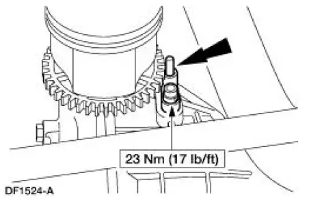
16. Install the driveshaft.
17. Install both mufflers.
18. Install both wheel and tire assemblies.
19. Remove the jack stand from the No. 1 crossmember.
20. Bleed the brake system.
21. Check wheel alignment. Adjust if necessary.
 Removal
CAUTION: Suspension fasteners are critical parts because they affect
performance of vital
components and systems and their failure can result in major service expense. A
new part with
the same part ...
 Shock Absorber
Removal
WARNING: All vehicles are equipped with gas pressurized shock absorbers
which will
extend unassisted. Do not apply heat or flame to the shock absorbers during
removal or
component servicing. ...
Other materials:
Retractor - Front Seat Safety Belt, Convertible
Special Tool(s)
Torx Bit, Safety Belt Bolt
501-010 (T77L-2100-A)
Removal
1. Remove the quarter trim panel (31012). For additional information, refer
to Section.
2. Remove the nut and bolts and safety belt retractor.
Installation
NOTE: Make ...
Air Conditioning (A/C) Pressure Relief Valve - 4.6L
Material
Item
Specification
PAG Refrigerant Compressor
Oil (R-134a Systems)
F7AZ-19589-DA (Motorcraft YN-
12-C)
WSH-M1C231-
B
Removal and Installation
NOTE: Installation of a new suction accumulator is not required when
repairing the ...
Pinpoint Tests
CAUTION: Before removing and installing the GEM or its connectors,
disconnect the
battery. Failure to follow this caution will result in the GEM storing many
erroneous DTCs and it
may exhibit erratic operation after installation.
CAUTION: Be careful when pr ...
