Ford Mustang (1999-2004) Service Manual: Fuel Tank Draining
Special Tool(s)
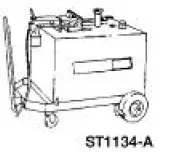 |
Fuel Storage Tanker 164-R3202 or equivalent |
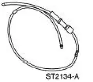 |
Fuel Tank Drain Hose 310-F013 |
WARNING: Do not smoke or carry lighted tobacco or an open flame of any type when working on or near any fuel-related components. Highly flammable mixtures are always present and may be ignited, resulting in possible personal injury.
1. Disconnect the battery ground cable. For additional information, refer to Section.
2. Remove the fuel tank filler cap.
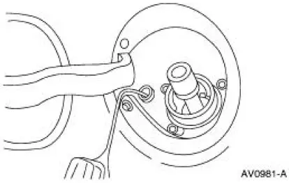
3. Insert the hose guide into the filler neck.
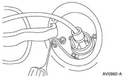
4. NOTE: Insert the hose until the stop contacts the guide tube. If the stop does not contact the guide tube, remove the hose and repeat the procedure.
Insert the chamfered end of the hose into the filler neck through the guide tube.
5. Attach the Fuel Storage Tanker to the hose and remove the fuel.
6. Remove the hose and the hose guide.
 Pressure Relief
Special Tool(s)
Fuel Pressure Gauge
310-012 (T80L-9974-B)
WARNING: Do not smoke or carry lighted tobacco or open flame of any
type when
working on or near any fuel-related components. ...
 Spring Lock Couplings
Special Tool(s)
Disconnect Tool, Spring Lock
Coupling (3/8 inch yellow)
310-D004 (D87L-9280-A) or
equivalent
Disconnect Tool, Spring Lock
Coupling (1/2 inch green)
310 ...
Other materials:
Touchscreen climate controls
Press the CLIMATE hard button to access your climate control features.
Depending on your vehicle line and option package, your climate screen
may look different from the screen shown here.
Climate Control Voice Commands
If you are not viewing the climate co ...
Parking, Rear and License Lamps
Refer to Wiring Diagrams Cell 92 , Exterior for schematic and connector
information.
Special Tool(s)
73 III Automotive Meter or
equivalent
105-R0057
Inspection and Verification
1. Verify the customer concern by operating the parking lamps ...
Installation
1. Align the center mark on the cover assembly to the V-notch on the rear
glass assembly and
staple the entire length of the number four bow.
2. Center the listing sleeve on the bottom of the folding top number two bow.
3. Position the listing sleeve onto ...
