Ford Mustang (1999-2004) Service Manual: Stabilizer Bar
Removal
CAUTION: Suspension fasteners are critical parts because they affect performance of vital components and systems and their failure can result in major service expense. A new part with the same part number must be installed if installation becomes necessary. If substitution is necessary, the part must be of the same finish and property class. Torque values must be used as specified during reassembly to make sure of correct retention of these parts.
1. Raise the vehicle.
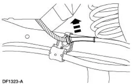
2. Disconnect the anti-lock brake sensor wires from the brackets.
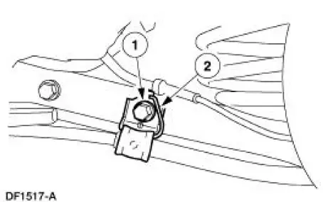
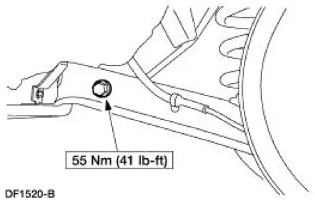
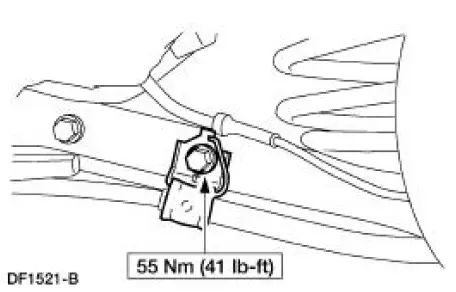
3. Remove the parking brake cable brackets.
1. Remove and discard the bolts.
2. Remove the parking brake cable brackets.
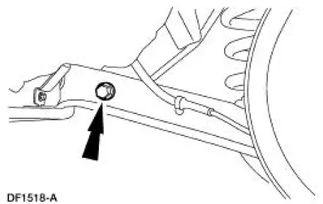
4. Remove the bolts and the stabilizer bar (5A772). Discard the bolts.
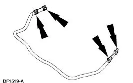
5. Remove and discard the nuts from the stabilizer bar.
Installation
NOTE: Make sure the rear stabilizer bar is not installed upside down. A color code is provided on the right (passenger) side only as an aid for correct positioning.
NOTE: Use new fasteners when installing the stabilizer bar.
1. To install, reverse the removal procedure.
 Lower Arm
Removal
CAUTION: Suspension fasteners are critical parts because they affect
performance of vital
components and systems and their failure can result in major service expense. A
new part with
the sa ...
 Stabilizer Bar - Cobra
Removal
CAUTION: Suspension fasteners are critical parts because they affect
performance of vital
components and systems and their failure can result in major service expense. A
new part with
the sa ...
Other materials:
Module Configuration
Module Configuration (Diagnosis and Testing)
Special Tool(s)
Worldwide Diagnostic System
(WDS)
418-F224
New Generation STAR (NGS)
Tester
418-F052 or equivalent
diagnostic tool
Principles of Operation
Some modules must be programme ...
Spark Plugs
Removal and Installation
1. Remove the ignition coil-on-plug. For additional information, refer to
Ignition Coil-On-Plug in this
section.
2. NOTE: Use compressed air to remove any foreign material from the
spark plug well before
removing the spark plu ...
Refueling
WARNING: Fuel vapor burns violently and a fuel fire can cause
severe injuries. To help avoid injuries to you and others:
• Read and follow all the instructions on the pump island.
• Turn off your engine when you are refueling.
• Do not smoke if you are n ...
