Ford Mustang (1999-2004) Service Manual: Lower Arm
Removal
CAUTION: Suspension fasteners are critical parts because they affect performance of vital components and systems and their failure can result in major service expense. A new part with the same part number must be installed if installation becomes necessary. If substitution is necessary, the part must be of the same finish and property class. Torque values must be used as specified during reassembly to make sure of correct retention of these parts.
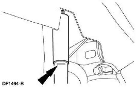
1. Mark the rear shock absorber (18125) relative to the protective sleeve with the vehicle in a static, level ground position (curb height).
2. Remove the muffler assembly(ies).
3. Remove the rear spring (5560). For additional information, refer to Spring-Coil in this section.
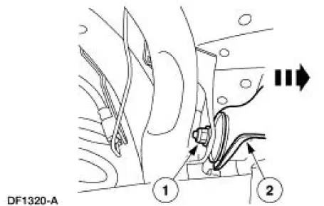
4. Remove the lower suspension arm and bushing (5A649) from the body attachment.
1. Remove and discard the bolt and nut.
2. Remove the lower arm.
Installation
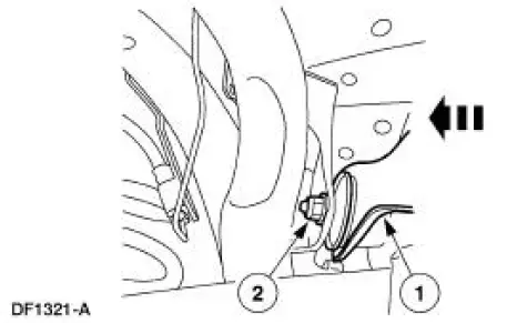
1. Install the lower suspension arm and bushing to the body attachment.
1. Position the lower arm.
2. Install a new bolt and a new nut. Do not tighten at this time.
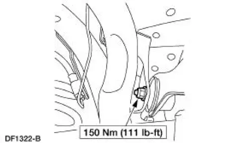
2. NOTE: Tighten the lower suspension arm and bushing-to-body attachment bolt after installing the spring while the suspension is at curb height.
Install the rear spring. For additional information, refer to Spring-Coil in this section.
3. Install the muffler assembly(ies).
 Installation
CAUTION: The upper suspension arm and bushing nuts must be tightened
with the
suspension at curb height. Failure to do so can result in bushing failure,
resulting in poor ride
and handling.
NOTE: If ...
 Stabilizer Bar
Removal
CAUTION: Suspension fasteners are critical parts because they affect
performance of vital
components and systems and their failure can result in major service expense. A
new part with
the sa ...
Other materials:
Car2U® home automation system
WARNING: Make sure that the garage door and security device
are free from obstruction when you are programming. Do not
program the system with the vehicle in the garage.
WARNING: Do not use the system with any garage door opener
that does not have the safety s ...
Windshield washers
Note: Do not operate the wipers on a dry windshield. This may scratch
the glass, damage the wiper blades or cause the wiper motor to burn out.
Always use the windshield washer before wiping a dry windshield.
Note: Do not operate the washer when the washer re ...
Lamp Assembly - Headlamp
Removal
1. NOTE: Make sure that the headlamp switch and the ignition switch are
in the OFF position.
Raise the headlamp retainers.
2. Remove the headlamp assembly.
Disconnect the electrical connectors and replace the lamp if
necessary.
Instal ...
