Ford Mustang (1999-2004) Service Manual: Supply Manifold
Removal and Installation
WARNING: Do not smoke or carry lighted tobacco or open flame of any type when working on or near any fuel related components. Highly flammable mixtures are always present and may ignite. Failure to follow these instructions may result in personal injury.
WARNING: Fuel in the fuel system remains under high pressure even when the engine is not running. Before working on or disconnecting any of the fuel lines or fuel system components, the fuel system pressure must be relieved. Failure to follow these instructions may result in personal injury.
1. Disconnect the battery ground cable.
2. Remove the upper intake manifold. For additional information, refer to Section.
3. Relieve the fuel pressure. For additional information, refer to Section.
4. Disconnect the fuel line. For additional information, refer to Section.
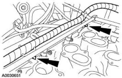
5. Separate the wiring harness from the supply manifold.
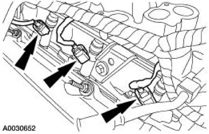
6. NOTE: Right side shown, left side similar.
Disconnect the six fuel injector electrical connectors.
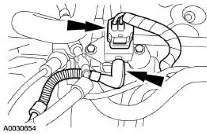
7. Disconnect the fuel pressure sensor.
- Disconnect the connector.
- Disconnect the vacuum hose.
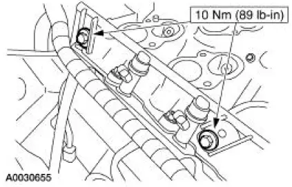
8. NOTE: The right side is shown. The left side is similar.
Remove the four supply manifold bolts and remove the fuel supply manifold with the injectors.
9. NOTE: When the battery (10655) is disconnect and reconnected, some abnormal drive symptoms may occur while the vehicle relearns its adaptive strategy. The vehicle may need to be driven 16 km (10 mi) or more to relearn the strategy.
To install, reverse the removal procedure.
 Fuel Charging Wiring Harness
Removal and Installation
WARNING: Do not smoke or carry lighted tobacco or open flame of any
type when
working on or near any fuel related components. Highly flammable mixtures are
always present
an ...
 Fuel Charging and Controls - 4.6L (2V)
General Specifications
Torque Specifications
...
Other materials:
Engine Support Insulators
Special Tool(s)
3 Bar Engine Support Kit
303-F072
Engine Lift Bracket Set
303-D095 (D94L-6001-A) or
equivalent
...
Digital Transmission Range (TR) Sensor
Special Tool(s)
Alignment Gauge, TR Sensor
307-351 (T97L-70010-A)
Removal
1. Disconnect the battery ground cable. For additional information, refer
to Section.
2. Raise and support the vehicle. For additional information, refer to
Sectio ...
Installation
NOTE: Do not use a fiber disc to clean the surfaces. Fibers from
the disc can get into the oil pan and
oil and clog the oil bypass valve.
1. Clean and inspect the cylinder head for flatness.
2. Install a new head gasket on the cylinder block with the sma ...
