Ford Mustang (1999-2004) Service Manual: Transmission (ASSEMBLY)
Special Tool(s)
|
|
Dial Indicator Gauge with Holding Fixture 100-002 (TOOL-4201-C) |
|
|
Rubber Tip Air Nozzle 100-D009 (D93L-7000-A) |
|
|
Alignment Gauge, TR Sensor 307-351 (T97L-70010-A) |
|
|
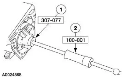
Slide Hammer 100-001 (T50T-100-A) |
|
|
Installer, Shift Shaft Fluid Seal 307-050 (T74P-77498-A) |
|
|
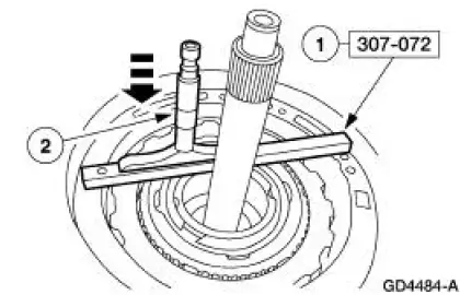
Shim Selection Gauge 307-072 (T80L-77003-A) |
|
|
Installer, Servo Piston 307-073 (T80L-77030-A) |
|
|
Remover/Installer, Transmission Extension Housing 307-077 (T80L-77110-A) |
|
|
Handle, Torque Converter 307-091 (T81P-7902-C) |
|
|
Test Plate Screw Set, Transmission 307-126 (T82P-7006-C) |
|
|
Air Test Plate, Transmission 307-246 (T92P-7006-A) |
|
|
Remover/Installer, Servo Piston 307-251 (T92P-70023-A) |
|
|
Retainer, Torque Converter 307-346 (T97T-7902-A) |
|
|
Installer, Transmission Extension Housing Oil Seal 308-002 (T61L-7657-A) |
|
|
Gauge, Transmission Solenoid Connectors 307-426 |
Material
| Item | Specification |
| Multi-Purpose Grease D0AZ-19584-AA | ESB-M1C93- B |
| MERCON V Automatic Transmission Fluid XT-5-QM, XT-5-DM | MERCON V |
CAUTION: Before beginning assembly, carry out and inspect the following: When building up subassemblies and assembling the transmission, ALWAYS use new gaskets and seals.
All fasteners must be tightened to the torque specification indicated. In addition to appearing in the section, the necessary torques can be found in the General Specifications Chart.
When building up subassemblies, each component part should be lubricated with clean transmission fluid. It is also good practice to lubricate the subassemblies as they are installed in the case.
Needle bearings, thrust washers and seals should be lightly coated with petroleum jelly during subassembly buildup or transmission assembly.
Many components and surfaces in the transmission are precision machined. Careful handling during disassembly, cleaning, inspection and assembly can prevent unnecessary damage to machined surfaces.
1. Use the special tools to install the rear case bushing if removed.
1. Position the rear case bushing and the special tool inside the case.
2. Assemble the special tools through the back of the case.
2. Place the transmission in the vertical position.
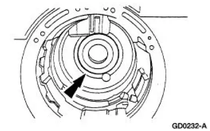
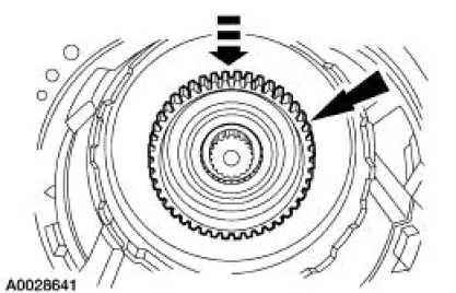
3. Coat the No. 9 case rear bearing with petroleum jelly and install on the case boss.
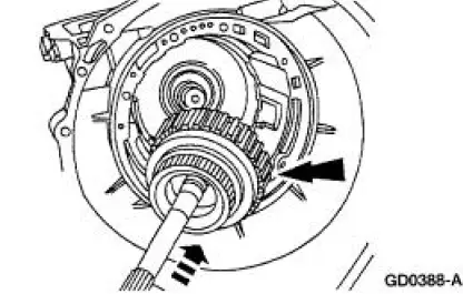
4. CAUTION: Be sure the No. 7 needle bearing and direct clutch hub are installed as shown in the Subassembly section. Internal damage and shift problems may occur.
Install the output shaft and output shaft ring gear.
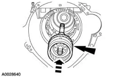
5. Install the No. 8 bearing
6. Install the direct clutch.
7. NOTE: The reverse band support retaining ring is used for assembly purposes during production. The reverse band support retaining ring is not required during assembly and it will not affect the operation of the transmission.
Install the reverse band support retaining ring.
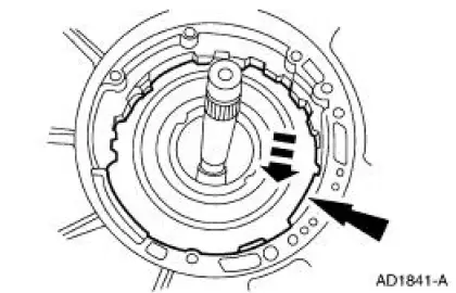
8. NOTE: Make sure the band is seated on the anchor pins.
Install the reverse band.
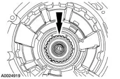
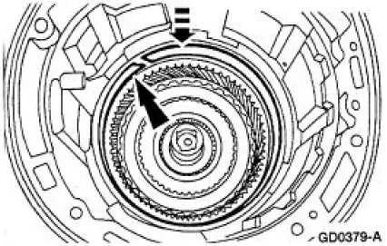
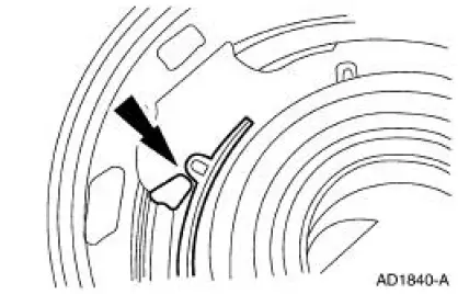
9. NOTE: The planetary assembly and planetary gear support cannot be installed unless the notch cut in the planetary gear support is aligned with the overdrive band anchor pin.
NOTE: The top of the planetary gear support must be below the snap ring groove.
Install the planetary assembly and planetary gear support as a unit.
- Rotate the output shaft to fully seat the planetary assembly.
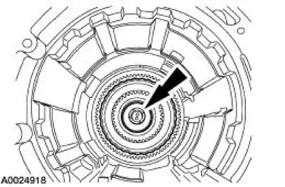
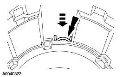
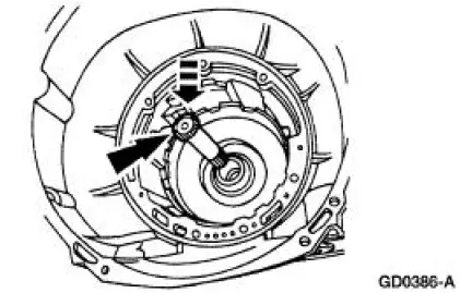
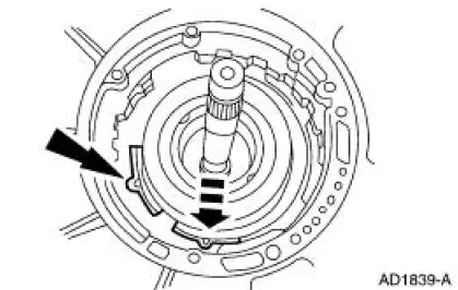
10. NOTE: The planet support spring must be compressed and installed below the snap ring groove. When the planet support spring is installed correctly both ends of the spring will be visible.
Install the case to the planet support spring located at the 1 o'clock position.
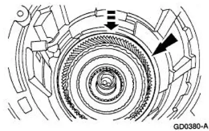
11. Install the center support retaining ring.
- Reference the retaining ring tabs to the band anchor pin location.
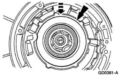
12. Install the forward clutch sun gear, the No. 5 forward clutch sun gear bearing and the reverse sun gear.
13. Install the No. 4 forward clutch hub bearing.
14. Install the intermediate stub shaft.
15. Install the forward clutch hub and the No. 3 forward clutch hub front bearing.
16. Install the forward clutch assembly.
17. NOTE: Make sure the reverse clutch cylinder lugs are completely seated in the notches of the reverse sun gear.
Install the reverse clutch cylinder assembly.
1. Install the reverse clutch cylinder.
2. Install the No. 2 forward clutch bearing.
18. Install the overdrive band.
- Position the overdrive band pocket onto the anchor pin.
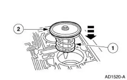
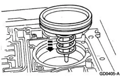
19. Install the overdrive servo spring.
1. Install the overdrive servo piston return spring.
2. Install the overdrive servo piston.
20. Verify the tip of the piston assembly engages the pocket of the overdrive band.
21. Using the special tool, compress the overdrive servo assembly and install the overdrive servo retaining ring.
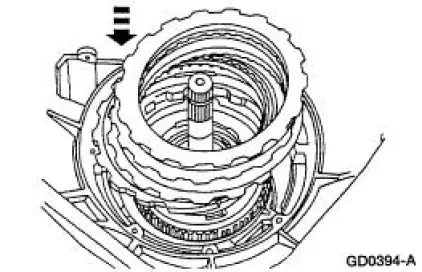
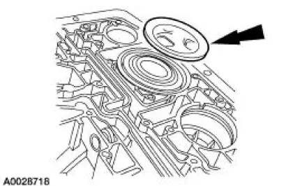
22. Install the intermediate clutch pressure plate.
23. NOTE: Before assembly, soak the new clutch discs in clean automatic transmission fluid for 15 minutes.
Install the intermediate clutch pack and selective steel plate.
24. Using the special tool, check the intermediate clutch clearance.
1. Position the special tool on the pump case mounting surface.
2. Maintaining downward pressure, use a depth micrometer to measure and verify intermediate clutch clearance is within specification.
If the intermediate clutch is not within specification, install a correct selective plate.
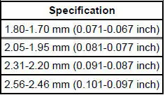
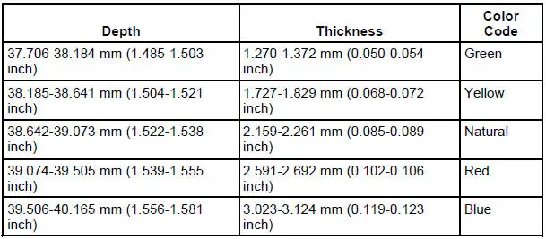
Selective Steel Plates
25. Install the intermediate anti-rattle clip, if equipped.
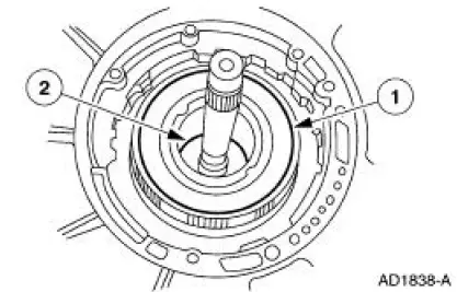
26. Using the special tool, measure end clearance for the No.1 front pump thrust washer.
1. Position the special tool on the pump case mounting surface.
2. Maintaining downward pressure, use a depth micrometer to measure end play clearance.
Use the No.1 thrust washer chart to select the correct washer.
No.1 Thrust Washer Chart
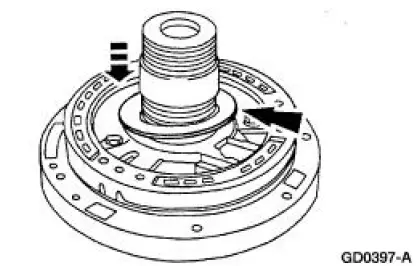
27. Install the No.1 front pump support thrust washer.
- Use petroleum jelly to hold the washer in place.
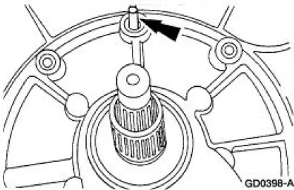
28. NOTE: The alignment pin is a fabricated M8 x 1.25 mm (0.05 in) bolt with the head removed.
Install an alignment pin at the top of the case.
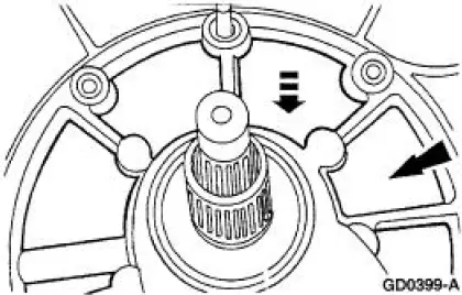
29. NOTE: Make sure the gasket is positioned correctly and the case passages are not covered.
Install the pump gasket.
30. NOTE: To aid assembly, shake the input shaft while pushing down on the pump.
Install the pump assembly.
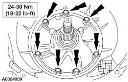
31. Remove the alignment pin and install the front pump bolts.
- Alternate bolt tightening to set the pump.
32. Rotate the transmission to the horizontal position.
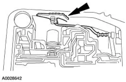
33. Install the parking pawl.
1. Position the parking pawl return spring.
2. Position the parking pawl.
3. Install the parking pawl shaft.
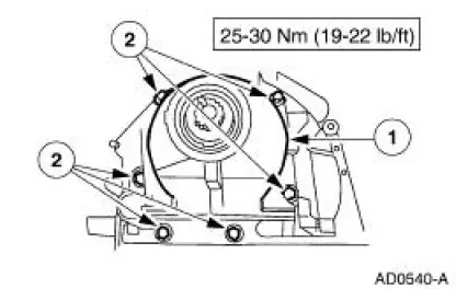
34. Install a new extension housing gasket and the extension housing.
1. Position the extension housing.
2. Install the four bolts and two nuts.
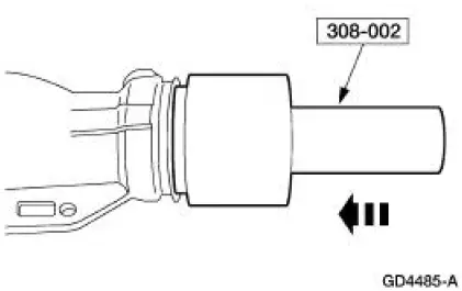
35. Using the special tool, install a new extension housing seal.
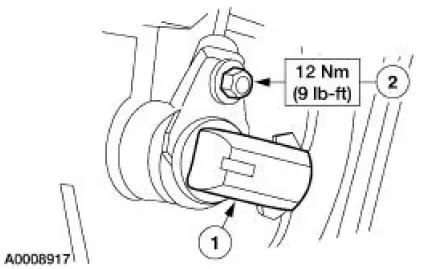
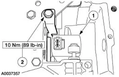
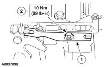
36. Install the output shaft speed (OSS) sensor.
1. Position the OSS sensor.
2. Install the bolt.
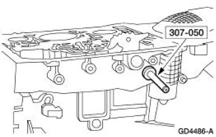
37. Using the special tool, install the manual control lever seal.
38. NOTE: Lubricate the electronic pressure control (EPC) solenoid O-rings with clean automatic transmission fluid.
Install the EPC solenoid.
1. Install the EPC solenoid.
2. Install the EPC solenoid bracket and bolt.
39. Install the manual valve detent lever and parking lever actuating rod.
40. Install the manual control lever shaft.
1. Slide the manual control shaft into the case.
2. Install the manual lever shaft inner nut.
3. Install the manual lever shaft retaining pin.
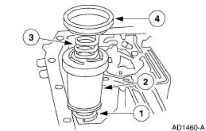
41. Install the 1-2 accumulator piston assembly.
1. Install the 1-2 accumulator upper spring.
2. Install the 1-2 accumulator.
3. Install the 1-2 accumulator lower spring.
4. Install the 1-2 accumulator cover and seal.
42. Install the 1-2 accumulator retaining ring.
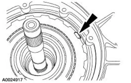
43. NOTE: This is not an ordinary installation procedure and does not compensate for band wear.
When new piston and rod assembly installation becomes necessary, or when a new reverse band has been installed, the reverse piston and rod length must be adjusted.
NOTE: Lubricate the reverse piston seal to facilitate assembly and prevent damage to the seal.
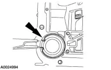
NOTE: Do not install the reverse servo piston cover and seal at this time.
Install the reverse servo piston and rod assembly.
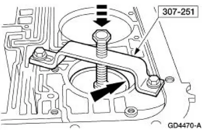
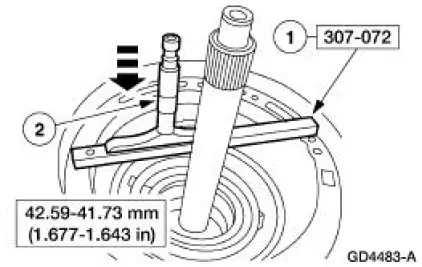
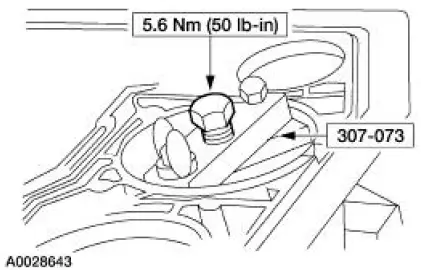
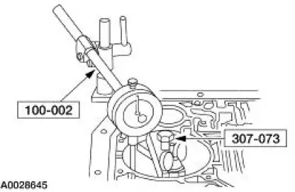
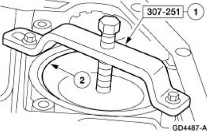
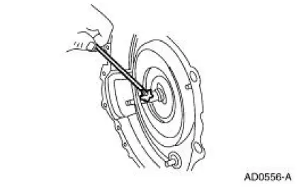
44. Install the special tool.
- Tighten the bolt.
45. Install the special tool.
- Position the indicator stem on the flat portion of the reverse servo piston and zero the dial indicator.
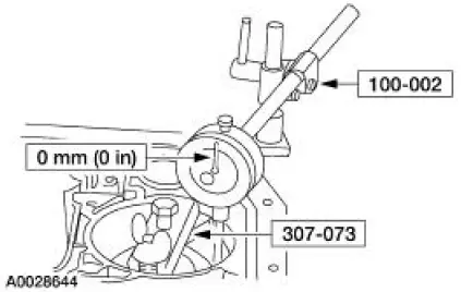
46. Loosen the bolt until the piston stops against the tool.
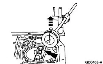
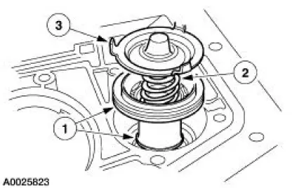
47. Verify that the amount of piston travel on the dial indicator is within specification.
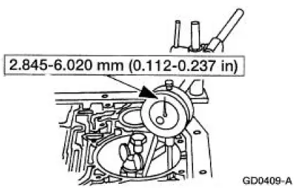
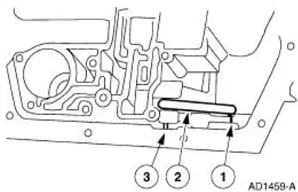
47. Verify that the amount of piston travel on the dial indicator is within specification.
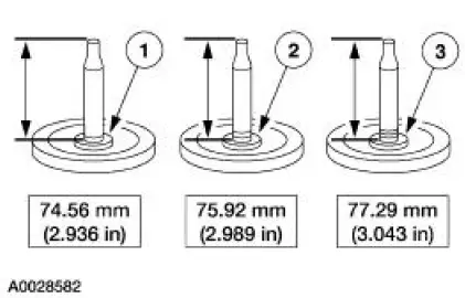
1. One groove
2. Two grooves
3. Three grooves
49. Remove the special tools.
50. Install the reverse servo piston cover and seal assembly.
51. Using the special tool, install the reverse servo retaining ring.
1. Compress the reverse band servo.
2. Install the reverse band servo retaining ring.
52. Install the 2-3 accumulator assembly.
1. Install the accumulator piston.
2. Install the accumulator piston spring.
3. Install the accumulator spring retainer.
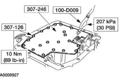
53. Using the special tools apply regulated air pressure to the test ports. Verify that the components are applied and released.
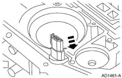
54. NOTE: The tab on the electrical connector is secured by main control valve body.
Install the electrical connector into the case.
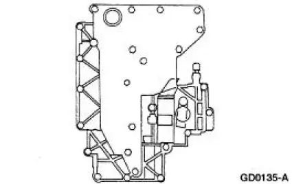
55. NOTE: The alignment bolts are valve body assembly bolts and are in the valve body.
Align the main control valve body alignment bolts and position the main control valve body.
56. NOTE: The main control valve body bolts will be tightened in later steps.
Loosely install the 11 long main control valve body bolts.
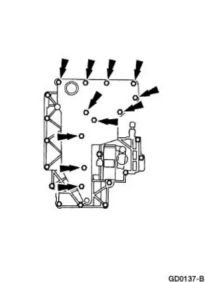
57. NOTE: The main control valve body bolts will be tightened in later steps.
Loosely install the 12 short main control valve body bolts.
58. Install the manual control valve detent lever spring.
1. Position the manual control valve detent lever spring.
2. Install the bolt.
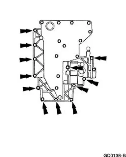
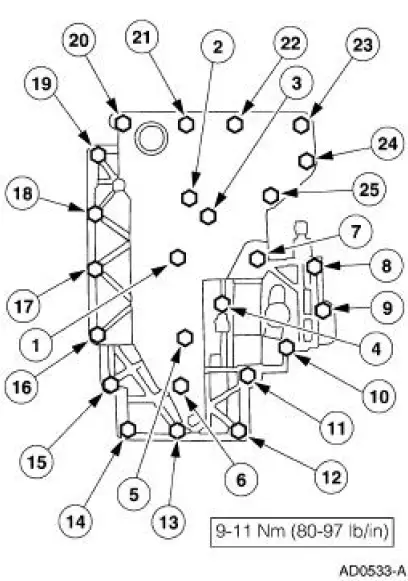
59. Tighten the bolts in the sequence shown.
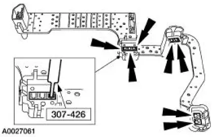
60. Inspect the lead frame for damage.
- Using the special tool, check all the lead frame solenoid connections. The gauge should fit tightly and not fall out after being inserted.
- If the special tool passes through any lead frame connector pins or does not feel like it makes a good contact, install a new lead frame.
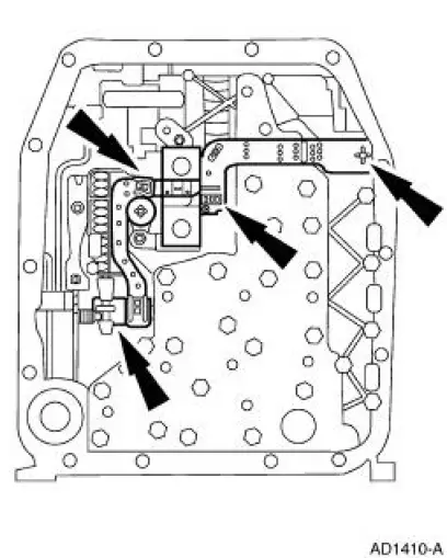
61. Connect the molded lead frame to the solenoids.
- Connect the bulkhead inter-connector by pressing it in place by hand and fully seating the connector in place.
- Connect the EPC solenoid by pressing it in place by hand and fully seating the connector in place. Make sure that the terminals pass fully through the connector slots.
- Connect the TCC by pressing it in place by hand and fully seating the
connector in place.
Make sure that the terminals pass fully through the connector slots.
- Connect the shift solenoid SSA and SSB by pressing it in place by hand and fully seating the connector in place. Make sure that the terminals pass fully through the connector slots.
62. Install the fluid filter and seal assembly.
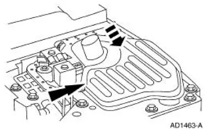
63. Position the pan magnet onto the fluid pan.
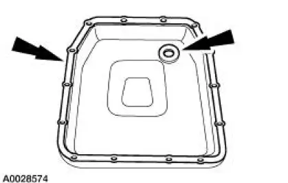
64. NOTE: The pan gasket is reusable; clean and inspect for damage. If not damaged, the gasket should be reused.
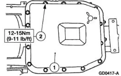
Install the fluid pan.
1. Position the transmission fluid pan.
2. Install the 14 transmission fluid pan bolts.
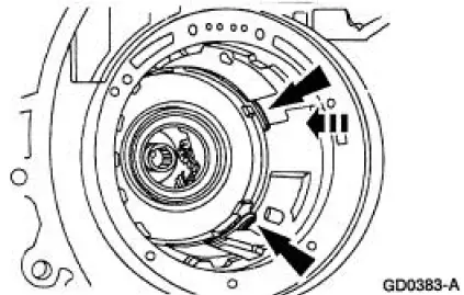
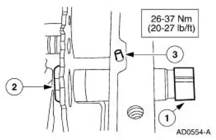
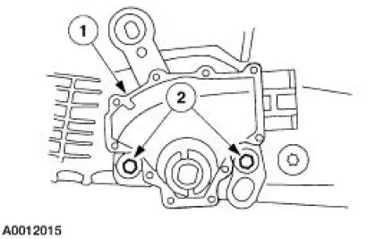
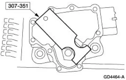
65. Install the digital transmission range (TR) sensor.
1. Install the digital TR sensor.
2. Loosely install the digital TR bolts.
66. NOTE: The tool is designed to fit snugly.
NOTE: Manual shift lever must be in the neutral position.
Using the special tool, align the digital TR sensor slots.
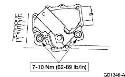
67. Tighten the bolts.
68. Lightly lubricate the converter hub with clean automatic transmission fluid.
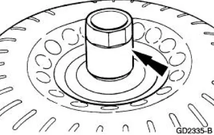
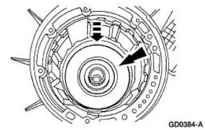
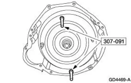
69. WARNING: The torque converter can fall out if the transmission is tipped.
CAUTION: Make sure the converter hub is fully engaged in the front pump support and gear and rotates freely. Do not damage the hub seal.
CAUTION: If the torque converter slides out, the hub seal may be damaged.
Using the special tools, install the torque converter.
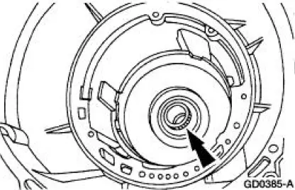
70. Lubricate the torque converter pilot hub with multi-purpose grease.
 Torque Converter Turbine to Pump Stator Interference
Check
Torque Converter Turbine to Pump Stator Interference
Check
1. NOTE: Front pump support may remain in front pump support and gear
during this test.
Position the torque converter with the pump drive up.
2. Install the front pump support to engage the mating sp ...
 Transmission (INSTALLATION)
Special Tool(s)
Retainer, Torque Converter
307-346 (T97T-7902-A)
Material
Item
Specification
Multi-Purpose Grease
D0AZ-19584-AA
ESB-M1C93-
B
MERCON V Automatic ...
Other materials:
Manual Transaxle/Transmission - T5OD
General Specifications
Torque Specifications
...
Auxiliary input jack
WARNING: Driving while distracted can result in loss of vehicle
control, crash and injury. We strongly recommend that you use
extreme caution when using any device that may take your focus off
the road. Your primary responsibility is the safe operation of your ...
Steering Column Switches (Diagnosis and Testing)
Refer to Wiring Diagrams Cell 13 , Power Distribution for schematic and
connector information.
Refer to Wiring Diagrams Cell 81 , Interval Wiper/Washer for schematic and
connector information.
Refer to Wiring Diagrams Cell 85 , Headlamps for schematic and co ...
