Ford Mustang (1999-2004) Service Manual: Transmission (INSTALLATION)
Special Tool(s)
|
|
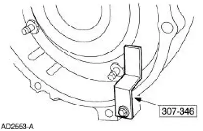
Retainer, Torque Converter 307-346 (T97T-7902-A) |
Material
| Item | Specification |
| Multi-Purpose Grease D0AZ-19584-AA | ESB-M1C93- B |
| MERCON V Automatic Transmission Fluid XT-5-QM, XT-5-DM | MERCON V |
1. CAUTION: During this move, to avoid damage, do not allow the transmission to get into a nose-down position as this will cause the torque converter to move forward and disengage from the pump gear. The converter housing is piloted into position by dowels in the rear of the engine block. The torque converter must rest squarely against the flexplate. This indicates that the converter pilot is not binding in the engine crankshaft.
Position and secure the transmission on the high-lift transmission jack.
2. CAUTION: Make sure the torque converter is fully seated in the transmission before positioning the transmission to the engine.
Using the special tool, install the transmission to the engine.
- Align the orange balancing marks on the converter stud and the flexplate bolt hole.
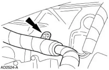
3. Reconnect the harness.
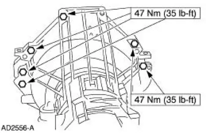
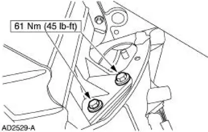
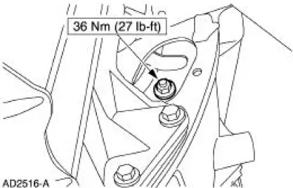
4. Install the bolts.
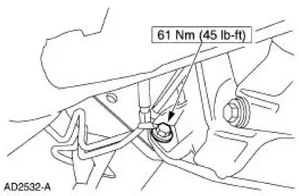
5. Install the bolt.
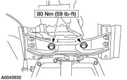
6. Install the bolts.
7. Install the bolts.
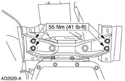
8. Install the bolts.
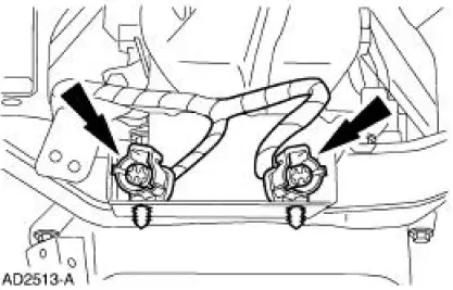
9. Reconnect the connectors.
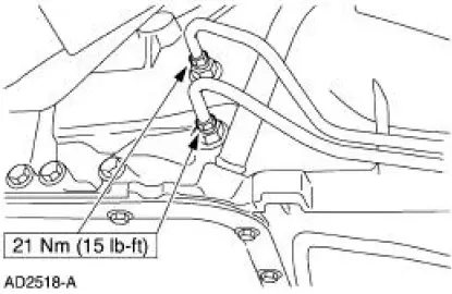
10. Connect the transmission fluid cooler tubes.
11. Install the shift cable.
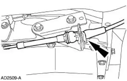
12. NOTE: The manual lever must be in the overdrive position.
Connect the shift cable at the manual lever.
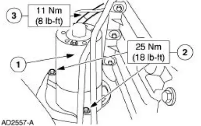
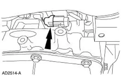
13. Install the starter.
1. Position the starter.
2. Install the bolts.
3. Connect the wires.
14. Install the four nuts.
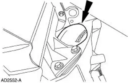
15. Install the cover.
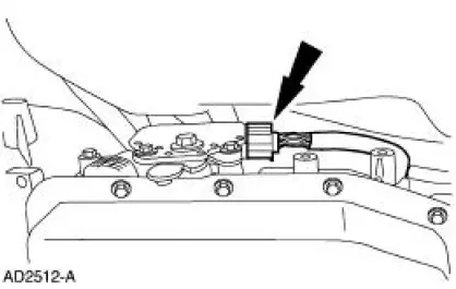
16. Reconnect the connector.
17. Reconnect the connector.
18. Install the dual converter Y pipe.
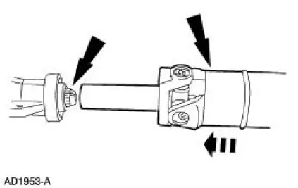
19. NOTE: The output shaft and the drive shaft are a balanced assembly.
Install the driveshaft.
- Align the yellow dots and position the driveshaft on the transmission.
- Position the driveshaft to the rear differential.
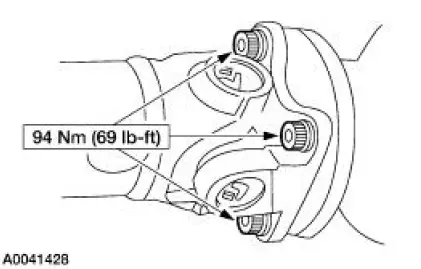
20. Install the bolts.
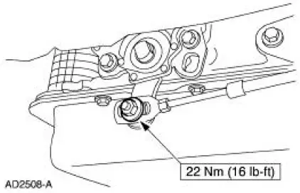
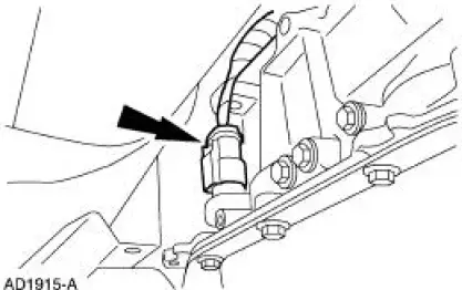
21. Connect the connector.
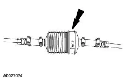
22. Use the following guidelines for the in-line transmission fluid filter:
- If the transmission was overhauled and the vehicle was equipped with an in-line fluid filter, install a new in-line fluid filter.
- If the transmission was overhauled and the vehicle was not equipped with an in-line fluid filter, install a new in-line fluid filter kit.
- If the transmission is being installed for a non-internal repair, do not install an in-line filter or filter kit.
- If installing a Ford authorized remanufactured transmission, install the
in-line
transmission fluid filter that is supplied.
Prior to lowering the vehicle, install a new in-line transmission filter or a filter kit.
23. NOTE: When the battery is disconnected and reconnected, some abnormal drive symptoms may occur while the vehicle relearns its adaptive strategy. The vehicle may need to be driven 16 km (10 miles) or more until the vehicle relearns the strategy.
Connect the battery ground cable.
24. If required, fill the transmission with clean automatic transmission fluid.
25. Check the transmission for correct operation.
 Transmission (ASSEMBLY)
Special Tool(s)
Dial Indicator Gauge with
Holding Fixture
100-002 (TOOL-4201-C)
Rubber Tip Air Nozzle
100-D009 (D93L-7000-A)
Alignment Gauge, TR Sensor
307-3 ...
 Transaxle/Transmission Cooling
General Specifications
Torque Specifications
...
Other materials:
Headlamps
Refer to Wiring Diagrams Cell 85 , Headlamps for schematic and
connector information.
Special Tool(s)
73III Automotive Meter or
equivalent
105-R0057
Inspection and Verification
1. Verify the customer concern by operating the headlamps. ...
Removal
WARNING: The restraints control module (RCM) orientation is critical
for proper system
operation. If a vehicle equipped with an air bag supplemental restraint system
(SRS) has been
involved in a collision in which the center tunnel area has been damaged,
in ...
Air Conditioning (A/C) Compressor Bracket - 3.8L
Removal and Installation
1. Remove the A/C compressor (19703). For additional information, refer to
Air Conditioning (A/C)
Compressor-3.8L in this section.
2. Remove the three bolts and one nut.
3. Remove the A/C compressor mounting bracket.
4. To install ...
