Ford Mustang (1999-2004) Service Manual: Transmission (Removal)
1. Disconnect the battery ground cable. For additional information, refer to Section.
2. Remove the gearshift lever knob.
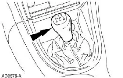
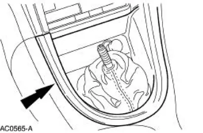
3. Remove the console panel gearshift plate. Lift the gearshift lever boot over the gearshift lever.
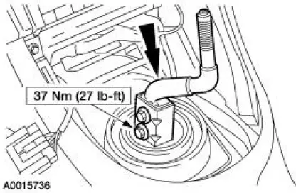
4. Remove the bolts and the shift lever.
5. With the vehicle in NEUTRAL, raise and support the vehicle.
6. Remove the dual converter H-pipe. For additional information, refer to Section.
7. CAUTION: Index-mark the driveshaft flange and pinion flange, and the driveshaft slip yoke and transmission output shaft.
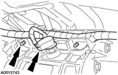
8. Disconnect the reversing lamp switch electrical connector. Disconnect the wiring harness from the transmission.
9. Remove the starter motor. For additional information, refer to Section.
10. Remove the bolts.
11. Remove the starter solenoid nuts and position the wires aside.
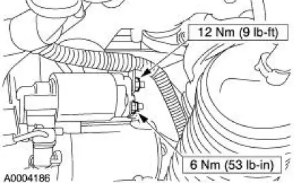
12. Remove the starter motor.
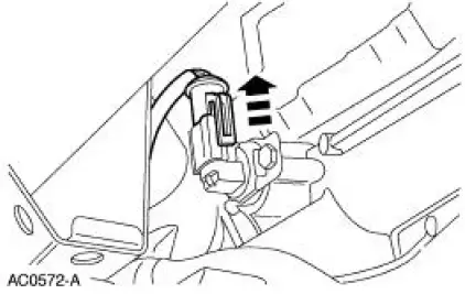
13. Disconnect the OSS sensor electrical connector. Disconnect the wiring harness from the transmission.
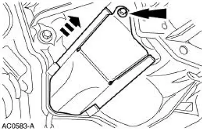
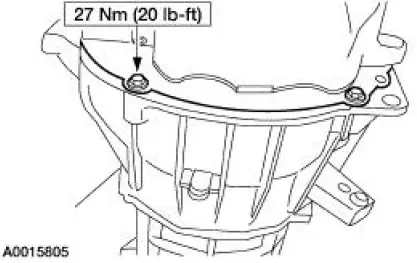
14. Remove the bolt and the clutch release lever cover.
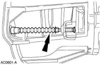
15. CAUTION: To prevent component damage, do not depress the clutch pedal with the transmission removed.
Disengage the clutch release cable from the clutch release fork.
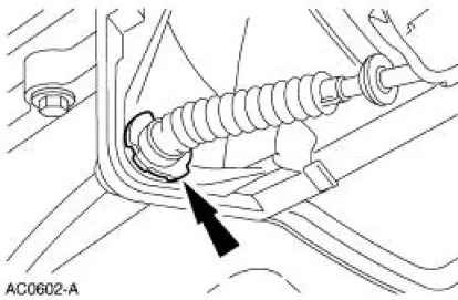
16. Remove the clutch cable retainer and remove the clutch cable from the transmission.
17. If transmission disassembly is necessary, drain the transmission fluid.
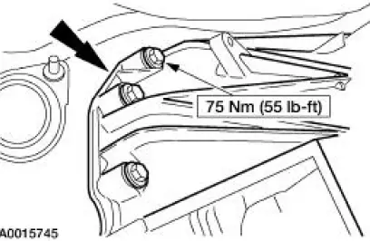
18. Position a transmission jack and support the transmission.
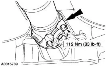
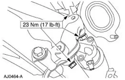
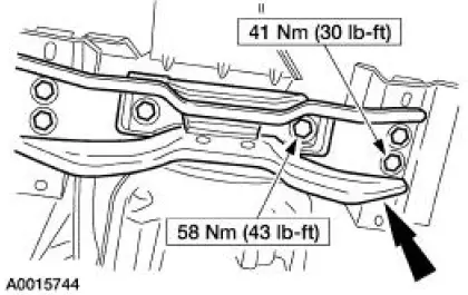
19. Remove the bolts and the transmission crossmember.
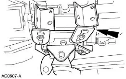
20. Remove the bolts.
21. Lower the transmission and remove the five bolts.
 Output Shaft Speed (OSS) Sensor
Removal and Installation
1. With the vehicle in NEUTRAL, raise and support the vehicle.
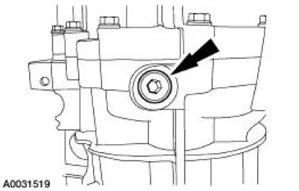
2. Disconnect the electrical connector.
3. Remove the output shaft speed (OSS) sensor.
4. To install, rever ...
 Transmission (Disassembly)
Special Tool(s)
Remover, Mainshaft Bearing
308-058 (T77J-7025-H)
Screw, Bearing Removal tube
308-092 (T84T-7025-B)
Holding Fixture, Transmission
307-003 (T57L- ...
Other materials:
Steering Column Switches
Torque Specifications
Steering Column Switches (DESCRIPTION AND OPERATION)
The steering column switches system consists of the following components:
multifunction switch (13K359)
key release button (manual transmission only) (3F527)
ignition switch (11572 ...
Belt Minder Deactivating/Activating
Preparation
1. Before deactivating/activating the belt minder, set the parking
brake.
2. Place the gearshift in P (Park) (automatic transmission) or the
neutral position (manual
transmission).
3. Place the ignition switch in the OFF position.
...
Halfshaft Joint
Special Tool(s)
Driver
205-199 (T83T-3132-A1)
Hub Bearing Cup Replacer
205-147 (T80T-4000-P)
Sensing Ring Replacer
206-041 (T89P-20202-A)
Disassembly
1. CAUTION: Do not disassemble the halfshaft assembly. Install a new
assem ...
