Ford Mustang (1999-2004) Service Manual: Visual Inspection Chart
|
Mechanical |
Electrical |
|
|
3. If the concern remains after the inspection, connect the scan tool to the data link connector (DLC) located beneath the instrument panel and select the vehicle to be tested from the scan tool menu. If the scan tool does not communicate with the vehicle:
1. Check that the program card is correctly installed.
2. Check the connections to the vehicle.
3. Check the ignition switch position.
4. If the scan tool still does not communicate with the vehicle, refer to the scan tool manual.
5. Carry out the DATA LINK DIAGNOSTIC TEST. If the scan tool responds with:
1. CKT914, CKT915 or CKT70 = ALL ECUS NO RESP/NOT EQUIP.
2. NO RESP/NOT EQUIP for the anti-lock brake control module, Go To Pinpoint Test A .
3. SYSTEM PASSED, retrieve and record the continuous diagnostic trouble codes (DTCs), erase the continuous DTCs and carry out self-test diagnostics for the anti-lock brake control module.
6. If the DTCs retrieved are related to the concern, go to the Anti-Lock Brake Control Module Diagnostic Trouble Code (DTC) Index to continue diagnostics.
7. If no DTCs related to the concern are retrieved, GO to Symptom Chart to continue diagnostics.
Anti-Lock Brake Control Module Diagnostic Trouble Code (DTC) Index
NOTE: If a wheel speed signal fault or a pump motor fault is detected, the yellow ABS warning indicator cannot be reset with the key OFF and key ON method. The vehicle must be driven over 12 km/h (8 mph) for the anti-lock brake control module to do a re-check of the system before the yellow ABS warning indicator is turned OFF.
Anti-Lock Brake Control Module Diagnostic Trouble Code (DTC) Index
| DTC | Description | Source | Action |
| B1318 | Battery Voltage Low | ABS/TC | Go To Pinpoint Test C . |
| B1342 | ECU Is Defective | ABS/TC | INSTALL a new anti-lock brake control module; REFER to Module . REPEAT the self-test. |
| B1484 | Brake Pedal Input Open Circuit | ABS/TC | Go To Pinpoint Test D . |
| B1596 | Repair Continuous Codes | ABS/TC | REPAIR the DTCs retrieved. |
| C1095 | ABS Hydraulic Pump Motor Circuit Failure | ABS/TC | Go To Pinpoint Test E . |
| C1145 | RF Anti-Lock Brake Sensor Input Circuit Failure | ABS/TC | Go To Pinpoint Test F . |
| C1155 | LF Anti-Lock Brake Sensor Input Circuit Failure | ABS/TC | Go To Pinpoint Test F . |
| C1165 | RR Anti-Lock Brake Sensor Input Circuit Failure | ABS/TC | Go To Pinpoint Test F . |
| C1175 | LR Anti-Lock Brake Sensor Input Circuit Failure | ABS/TC | Go To Pinpoint Test F . |
| C1222 | Anti-Lock Brake Sensor Mismatch | ABS/TC | Go To Pinpoint Test G . |
| C1233 | LF Anti-Lock Brake Sensor Input Signal Missing | ABS/TC | Go To Pinpoint Test H . |
| C1234 | RF Anti-Lock Brake Sensor Input Signal Missing | ABS/TC | Go To Pinpoint Test H . |
| C1235 | RR Anti-Lock Brake Sensor Input Signal Missing | ABS/TC | Go To Pinpoint Test H . |
| C1236 | LR Anti-Lock Brake Sensor Input Signal Missing | ABS/TC | Go To Pinpoint Test H . |
| C1266 | ABS Valve Power Relay Circuit Failure | ABS/TC | INSTALL a new anti-lock brake control module; REFER to Module . REPEAT the self-test. |
| C1805 | Mismatched PCM and/or Anti-Lock Brake Control Module | ABS/TC | CLEAR the DTCs. RETRIEVE the DTCs. If DTC C1805 is retrieved, check the PCM and Anti-Lock Brake Control Module is for the correct vehicle. INSTALL a new PCM or anti-lock brake control module as necessary. CLEAR the DTCs. REPEAT the self-test. |
| U1009 | SCP (J1850) Invalid or Missing Data for Engine Torque | ABS/TC | CARRY OUT the PCM self-test. |
| U1027 | SCP (J1850) Invalid or Missing Data for Engine RPM | ABS/TC | CARRY OUT the PCM self-test. |
| U1059 | SCP (J1850) Invalid or Missing Data for Transmission/Transaxle/PRNDL | ABS/TC | CARRY OUT the PCM self-test. |
| U1083 | SCP (J1850) Invalid or Missing Data for Engine Systems | ABS/TC | CARRY OUT the PCM self-test. |
| U1262 | SCP (J1850) Communication Bus Fault | ABS/TC |
Anti-Lock Brake Control Module Parameter Identification (PID) Index
| PID | Description | Expected Value |
| CCNTABS | Number of Continuous DTCS in the Anti-Lock Brake Control Module | one count per bit |
| BOO_ABS | Brake Switch Input | OFF, ON |
| PMP_MTR | ABS Pump Motor | OFF---, OFFO--, OFF-B-, OFF--G, OFFO-G, OFFBG, OFFOBG, ON---, ONO--, ON-B-, ON--G, ONOG, ON-BG, ONOBG |
| VLV_CTR | ABS Valve Control Relay | OFF---, OFFO--, OFF-B-, OFF--G, OFFO-G, OFFBG, OFFOBG, ON---, ONO--, ON-B-, ON--G, ONOG, ON-BG, ONOBG |
| LF_WSPD | LF Wheel Speed | 0-255 MPH |
| RF_WSPD | RF Wheel Speed | 0-255 MPH |
| LR_WSPD | LR Wheel Speed | 0-255 MPH |
| RR_WSPD | RR Wheel Speed | 0-255 MPH |
| ABSLF_I | LF ABS Inlet Valve | OFF---, OFFO--, OFF-B-, OFF--G, OFFO-G, OFFBG, OFFOBG, ON---, ONO--, ON-B-, ON--G, ONOG, ON-BG, ONOBG |
| ABSLF_O | LF ABS Outlet Valve | OFF---, OFFO--, OFF-B-, OFF--G, OFFO-G, OFFBG, OFFOBG, ON---, ONO--, ON-B-, ON--G, ONOG, ON-BG, ONOBG |
| ABSRF_I | RF ABS Inlet Valve | OFF---, OFFO--, OFF-B-, OFF--G, OFFO-G, OFFBG, OFFOBG, ON---, ONO--, ON-B-, ON--G, ONOG, ON-BG, ONOBG |
| ABSRF_O | RF ABS Outlet Valve | OFF---, OFFO--, OFF-B-, OFF--G, OFFO-G, OFFBG, OFFOBG, ON---, ONO--, ON-B-, ON--G, ONOG, ON-BG, ONOBG |
| ABSLR_I | LR ABS Inlet Valve | OFF---, OFFO--, OFF-B-, OFF--G, OFFO-G, OFFBG, OFFOBG, ON---, ONO--, ON-B-, ON--G, ONOG, ON-BG, ONOBG |
| ABSLR_O | LR ABS Outlet Valve | OFF---, OFFO--, OFF-B-, OFF--G, OFFO-G, OFFBG, OFFOBG, ON---, ONO--, ON-B-, ON--G, ONOG, ON-BG, ONOBG |
| ABSRR_I | RR ABS Inlet Valve | OFF---, OFFO--, OFF-B-, OFF--G, OFFO-G, OFFBG, OFFOBG, ON---, ONO--, ON-B-, ON--G, ONOG, ON-BG, ONOBG |
| ABSRR_O | RR ABS Outlet Valve | OFF---, OFFO--, OFF-B-, OFF--G, OFFO-G, OFFBG, OFFOBG, ON---, ONO--, ON-B-, ON--G, ONOG, ON-BG, ONOBG |
| LF_TC_P | LF Traction Control Priming Valve | OFF, ON |
| RF_TC_P | RF Traction Control Priming Valve | OFF, ON |
| LR_TC_P | LR Traction Control Priming Valve | OFF, ON |
| RR_TC_P | RR Traction Control Priming Valve | OFF, ON |
| LF_TC_S | LF Traction Control Switching Valve | OFF, ON |
| RF_TC_S | RF Traction Control Switching Valve | OFF, ON |
| LR_TC_S | LR Traction Control Switching Valve | OFF, ON |
| RR_TC_S | RR Traction Control Switching Valve | OFF, ON |
| T/ALVAL | Left Traction Control Valve Output State | OFF---, OFFO--, OFF-B-, OFF--G, OFFO-G, OFFBG, OFFOBG, ON---, ONO--, ON-B-, ON--G, ONOG, ON-BG, ONOBG |
| T/ARVAL | Right Traction Control Valve Output State | OFF---, OFFO--, OFF-B-, OFF--G, OFFO-G, OFFBG, OFFOBG, ON---, ONO--, ON-B-, ON--G, ONOG, ON-BG, ONOBG |
Anti-Lock Brake Control Module Active Command Index
| Active Command | Display | Action |
| ABS OUTPUT CONTROL | ABS POWER | OFF, ON |
| DSBL TOG | OFF, ON | |
| LF INLET | OFF, ON | |
| LF OUTLET | OFF, ON | |
| RF INLET | OFF, ON | |
| RF OUTLET | OFF, ON | |
| LR INLET | OFF, ON | |
| LR OUTLET | OFF, ON | |
| RR INLET | OFF, ON | |
| RR OUTLET | OFF, ON | |
| TRACTION CONTROL PRIMARY AND SWITCHING VALVE CONTROL | LF TC PRV | OFF, ON |
| LF TC SWV | OFF, ON | |
| RF TC PRV | OFF, ON | |
| RF TC SWV | OFF, ON | |
| LR TC PRV | OFF, ON | |
| LR TC SWV | OFF, ON | |
| RR TC PRV | OFF, ON | |
| RR TC SWV | OFF, ON |
Symptom Chart
NOTE: Refer to the wiring diagrams for connector numbers stated in the pinpoint test.
| Condition | Possible Sources | Action |
|
|
|
|
|
|
|
|
|
|
|
|
|
|
|
|
|
|
|
|
|
Pinpoint Tests
PINPOINT TEST A: NO COMMUNICATION WITH THE ANTI-LOCK BRAKE CONTROL MODULE
| Test Step | Result / Action to Take |
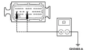
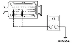
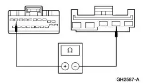
| A1 CHECK CIRCUIT 601 (LB/PK) FOR AN OPEN | Yes GO to A2 . No REPAIR the circuit. REPEAT the selftest. |
|
|
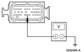
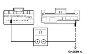
| A2 CHECK THE ANTI-LOCK BRAKE CONTROL MODULE GROUNDS | Yes INSTALL a new anti-lock brake control module; REFER to Module . REPEAT the selftest. No REPAIR the circuit in question. REPEAT the selftest. |
|
PINPOINT TEST B: UNABLE TO ENTER SELF-TEST
| Test Step | Result / Action to Take |
| B1 CHECK THE COMMUNICATIONS TO THE ANTI-LOCK BRAKE CONTROL MODULE | Yes INSTALL a new anti-lock brake control module; REFER to Module . REPEAT the self-test. No Go To Pinpoint Test A . |
|
PINPOINT TEST C: DTC B1318, BATTERY VOLTAGE LOW
| Test Step | Result / Action to Take |
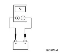
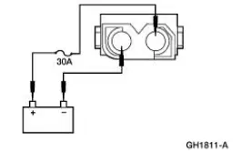
| C1 CHECK BATTERY VOLTAGE | Yes GO to C2 . No |
|
|
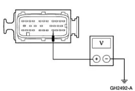
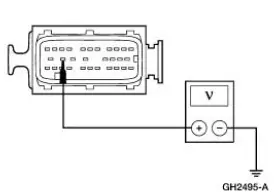
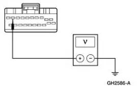
| C2 CHECK THE VOLTAGE TO THE ANTI-LOCK BRAKE CONTROL MODULE | Yes GO to C3 . No REPAIR the circuit. CLEAR the DTCs. REPEAT the selftest. |
|
|
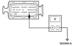
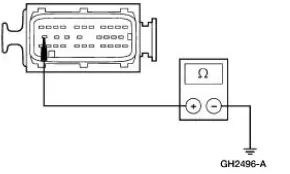
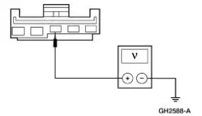
| C3 CHECK THE ANTI-LOCK BRAKE CONTROL MODULE GROUNDS | Yes INSTALL a new anti-lock brake control module; REFER to Module . REPEAT the selftest. No REPAIR the circuit in question. CLEAR the DTCs. REPEAT the selftest. |
|
PINPOINT TEST D: DTC B1484, BRAKE PEDAL INPUT OPEN CIRCUIT
| Test Step | Result / Action to Take |
| D1 CHECK THE STOPLAMPS FOR CORRECT OPERATION | Yes GO to D2 . No |
|
|
| D2 CHECK THE BRAKE PEDAL INPUT TO THE ANTI-LOCK BRAKE CONTROL MODULE | Yes INSTALL a new anti-lock brake control module; REFER to Module . REPEAT the self-test. No REPAIR Circuit 511 (LG) and Circuit 810 (RD/LG) as necessary. CLEAR the DTCs. REPEAT the self-test. |
|
PINPOINT TEST E: DTC C1095, ABS HYDRAULIC PUMP MOTOR FAILURE
| Test Step | Result / Action to Take |
| E1 CHECK THE PUMP MOTOR FOR CONTINUOUS OPERATION | Yes INSTALL a new anti-lock brake control module; REFER to Module . REPEAT the selftest. No GO to E2 . |
|
|
| E2 CHECK CIRCUIT 534 (YE/LG) FOR AN OPEN | Yes GO to E3 . No REPAIR the circuit. CLEAR the DTCs. REPEAT the selftest. |
|
|
| E3 CHECK CIRCUIT 1205 (BK) FOR AN OPEN | Yes GO to E4 . No REPAIR the circuit. CLEAR the DTCs. REPEAT the selftest. |
|
|
| E4 CHECK THE PUMP MOTOR FOR OPERATION | Yes INSTALL a new anti-lock brake control module; REFER to Module . REPEAT the selftest. No INSTALL a new HCU; REFER to Hydraulic Control Unit . CLEAR the DTCs. REPEAT the self-test. |
|
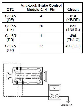
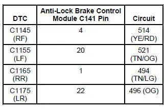
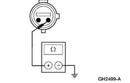
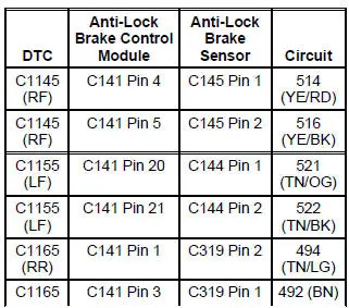
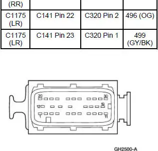
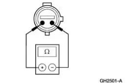
PINPOINT TEST F: DTC C1145 (RF), C1155 (LF), C1165 (RR), C1175 (LR), ANTI-LOCK BRAKE SENSOR INPUT CIRCUIT FAILURE
| Test Step | Result / Action to Take |
| F1 CHECK THE SUSPECT ANTI-LOCK BRAKE SENSOR CIRCUIT FOR SHORT TO POWER | Yes REPAIR the circuit in question. CLEAR the DTCs. REPEAT the self-test. No GO to F2 . |
|
|
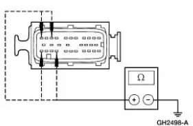
| F2 CHECK THE SUSPECT ANTI-LOCK BRAKE SENSOR CIRCUIT FOR SHORT TO GROUND | Yes GO to F4 . No GO to F3 . |
|
|
| F3 CHECK THE SUSPECT ANTI-LOCK BRAKE SENSOR FOR A SHORT TO GROUND | Yes If RF, REPAIR Circuit 514 (YE/RD) and Circuit 516 (YE/BK), as necessary. CLEAR the DTCs. REPEAT the self-test. If LF, REPAIR Circuit 521 (TN/OG) and Circuit 522 (TN/BK), as necessary. CLEAR the DTCs. REPEAT the self-test. If RR, REPAIR Circuit 494 (TN/LG) and Circuit 492 (BN), as necessary. CLEAR the DTCs. REPEAT the selftest. If LR, REPAIR Circuit 496 (OG) and Circuit 499 (GY/BK), as necessary. CLEAR the DTCs. REPEAT the self-test. No INSTALL a new anti-lock brake sensor; REFER to Sensor-Front or Sensor-Rear . CLEAR the DTCs. REPEAT the self-test. |
|
|
| F4 CHECK THE SUSPECT ANTI-LOCK BRAKE SENSOR CIRCUIT FOR FOR AN OPEN | Yes GO to F5 . No REPAIR the circuit in question. CLEAR the DTCs. REPEAT the selftest. |
|
|
| F5 CHECK THE ANTI-LOCK BRAKE SENSOR | Yes INSTALL a new anti-lock brake control module; REFER to Module . REPEAT the self-test. No INSTALL a new anti-lock brake sensor; REFER to Sensor-Front or Sensor-Rear . CLEAR the DTCs. REPEAT the self-test. |
|
PINPOINT TEST G: DTC C1222, ANTI-LOCK BRAKE SENSOR MISMATCH
| Test Step | Result / Action to Take |
| G1 CHECK THE VEHICLE COMPONENTS | Yes GO to G2 . No REPAIR as necessary. CLEAR the DTCs. REPEAT the self-test. |
|
|
| G2 TEST DRIVE THE VEHICLE | Yes INSTALL a new anti-lock brake control module; REFER to Module . REPEAT the self-test. No If another DTC is retrieved, GO to the Anti-Lock Brake Control Module Diagnostic Trouble Code (DTC) index. If no DTCs are retrieved, system is OK. |
|
PINPOINT TEST H: DTC C1233 (LF), C1234 (RF), C1235 (RR), C1236 (LR), ANTI-LOCK BRAKE SENSOR INPUT SIGNAL MISSING
| Test Step | Result / Action to Take |
| H1 CHECK THE SUSPECT ANTI-LOCK BRAKE SENSOR | Yes GO to H2 . No REPAIR as necessary. CLEAR the DTCs. REPEAT the self-test. |
|
|
| H2 CHECK THE SUSPECT ANTI-LOCK BRAKE SENSOR INDICATOR | Yes GO to H3 . No INSTALL a new anti-lock brake sensor indicator; REFER to Sensor Indicator- Front or Sensor Indicator-Rear . CLEAR the DTCs. REPEAT the self-test. |
|
|
| H3 CHECK THE ANTI-LOCK BRAKE SENSOR OUTPUT | Yes INSTALL a new anti-lock brake control module; REFER to Module . REPEAT the self-test. No INSTALL a new anti-lock brake sensor; REFER to Sensor-Front or Sensor- Rear . CLEAR the DTCs. REPEAT the self-test. |
|
PINPOINT TEST I: THE YELLOW ABS WARNING INDICATOR DOES NOT SELF-CHECK
| Test Step | Result / Action to Take |
| I1 CHECK THE ABS WARNING INDICATOR CIRCUITRY | Yes INSTALL a new anti-lock brake control module; REFER to Module . TEST the system for normal operation. No |
|
PINPOINT TEST J: SPONGY BRAKE PEDAL WITH NO WARNING INDICATOR
| Test Step | Result / Action to Take |
| J1 CHECK THE VEHICLE COMPONENTS | Yes GO to J2 . No REPAIR as necessary. TEST the system for normal operation. |
|
|
| J2 BLEED THE BRAKE SYSTEM | Yes INSTALL a new HCU; REFER to Hydraulic Control Unit . TEST the system for normal operation. No The brake system is OK. TEST the system for normal operation. |
|
PINPOINT TEST K: POOR VEHICLE TRACKING DURING ANTI-LOCK FUNCTION
| Test Step | Result / Action to Take |
| K1 BLEED THE BRAKE SYSTEM | Yes GO to K2 . No The brake system is OK. TEST the system for normal operation. |
|
|
| K2 CHECK THE LF ABS VALVE OPERATION | Yes INSTALL a new HCU; REFER to Hydraulic Control Unit . TEST the system for normal operation. No GO to K3 . |
|
|
| K3 CHECK THE LF ABS VALVE RELEASE | Yes GO to K4 . No GO to K10 . |
|
|
| K4 CHECK THE RF ABS VALVE OPERATION | Yes INSTALL a new HCU; REFER to Hydraulic Control Unit . TEST the system for normal operation. No GO to K5 . |
|
|
| K5 CHECK THE RF ABS VALVE RELEASE | Yes GO to K6 . No GO to K10 . |
|
|
| K6 CHECK THE LR ABS VALVE OPERATION | Yes INSTALL a new HCU; REFER to Hydraulic Control Unit . TEST the system for normal operation. No GO to K7 . |
|
|
| K7 CHECK THE LR ABS VALVE RELEASE | Yes GO to K8 . No GO to K10 . |
|
|
| K8 CHECK THE RR ABS VALVE OPERATION | Yes INSTALL a new HCU; REFER to Hydraulic Control Unit . TEST the system for normal operation. No GO to K9 . |
|
|
| K9 CHECK THE RR ABS VALVE RELEASE | Yes The ABS system is operating correctly. No GO to K10 . |
|
|
| K10 CHECK FOR DTCS | Yes GO to the Anti-Lock Brake Control Module Diagnostic Trouble Code (DTC) Index. No INSTALL a new HCU; REFER to Hydraulic Control Unit . TEST the system for normal operation. |
|
PINPOINT TEST L: THE TRACTION CONTROL IS INOPERATIVE- DOES NOT OPERATE CORRECTLY
| Test Step | Result / Action to Take |
| L1 CHECK THE TRACTION CONTROL SWITCH CIRCUITRY | Yes INSTALL a new instrument cluster. TEST the system for normal operation. No GO to L2 . |
|
|
| L2 CHECK CIRCUIT 959 (GY) FOR AN OPEN | Yes GO to L3 . No REPAIR the circuit. TEST the system for normal operation. |
|
|
| L3 CHECK CIRCUIT 489 (PK/BK) FOR AN OPEN | Yes INSTALL a new traction control switch. TEST the system for normal operation. No REPAIR the circuit. TEST the system for normal operation. |
|
PINPOINT TEST M: THE TRACTION CONTROL INDICATOR IS INOPERATIVE-TRACTION CONTROL SWITCH
| Test Step | Result / Action to Take |
| M1 CHECK CIRCUIT 960 (BK/LB) | Yes GO to M2 . No |
|
|
| M2 CHECK CIRCUIT 489 (PK/BK) FOR AN OPEN | Yes GO to M3 . No REPAIR the circuit. TEST the system for normal operation. |
|
|
| M3 CHECK THE TRACTION CONTROL SWITCH INDICATOR | Yes INSTALL a new instrument cluster. TEST the system for normal operation. No INSTALL a new traction control switch. TEST the system for normal operation. |
|
Other materials:
Valve Spring Strength
Special Tool(s)
Pressure Gauge, Valve/Clutch
Spring
303-006 (TOOL-6513-DD) or
equivalent
1. Use a Valve/Clutch Spring Pressure Gauge to check the valve spring for
correct strength at the
specified valve spring length.
Refer to the appr ...
Oil Level Indicator and Tube
Removal and Installation
1. Remove the oil level indicator tube (6754).
Remove the bolt.
Remove the oil level indicator tube.
Remove and discard the oil level indicator tube O-ring.
2. To install, reverse the removal procedure.
...
Installation
1. Install the upper intake manifold gasket.
2. Install the intake manifold and bolts in the sequence shown.
3. Install the PCV valve-to-intake manifold tube.
4. Connect the vacuum hoses and the electrical connector to the EGR vacuum
regulator soleno ...
