Ford Mustang (1999-2004) Service Manual: Wheel And Tire
Removal
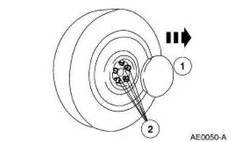
1. CAUTION: Do not use heat to loosen a seized wheel nut (1012). Heat can damage the wheel and wheel bearings.
NOTE: To avoid damage or scratching to the center cap, place facing up when removed.
Loosen the wheel nuts.
1. NOTE: To avoid wheel damage, do not twist wrench when removing center cap.
Remove the center cap, if equipped.
2. Loosen, but do not remove, the wheel nuts.
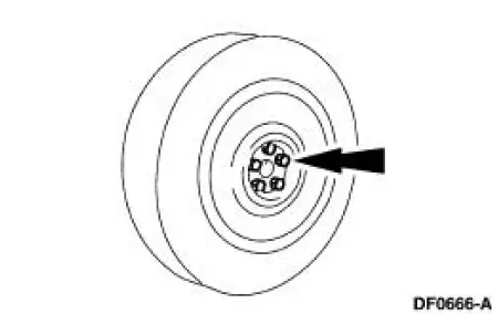
2. CAUTION: Never use the differential housing as a lifting point.
Raise the vehicle until the tire clears the ground.
3. CAUTION: Do not use heat to loosen a seized wheel because heat can shorten the life of the wheel and damage the wheel bearings. If the wheel cannot be removed by hand, use a wheel puller to remove the seized wheel.
Remove the wheel and tire assembly.
- Remove the wheel nuts.
- Remove the wheel and tire.
Installation
1. WARNING: When a wheel is installed, always remove any corrosion, dirt or foreign material present on the mounting surfaces of the wheel and the surface of the wheel hub, brake drum or brake disc that contacts the wheel. Installing wheels without correct metal-to-metal contact at the wheel mounting surfaces can cause the wheel nuts to loosen and the wheel to come off while the vehicle is in motion, causing loss of control.
Position the wheel and tire on the vehicle.
2. CAUTION: Failure to tighten the wheel nuts in a star pattern can result in high brake disc runout, which will speed up the development of brake roughness, shudder and vibration.
Install the wheel nuts hand-tight, then lower the vehicle. Tighten the wheel nuts to specification in a star-pattern sequence.
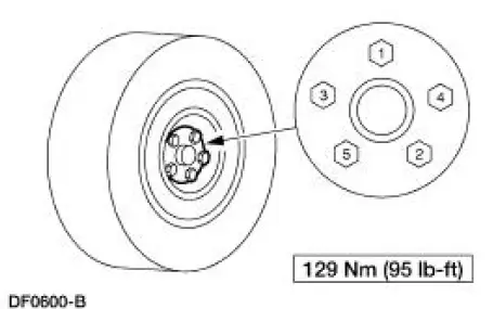
3. Install the center cap, if so equipped.
 Wheel Leaks
Material
Item
Specification
Professional Choke and
Linkage Cleaner
F8AZ-19520-AB
WSS-M14P10-
B
Aluminum Wheel Repair
Compound
ESA-M4G280-
A
WARNING: Wheel repairs t ...
 Driveline
...
Other materials:
Inspection and Verification
1. Verify the customer concern.
2. Visually inspect for obvious signs of electrical damage.
Visual Inspection Chart
Electrical
Central junction box (CJB) Fuse 31 (5A)
Damaged wiring harness
Loose or corroded connections
...
Underbody Misalignment Check
Underbody Dimensions
1. Underbody dimensions tolerances are +- 3.175 mm (0.125 in). Reference
dimensions are not
controlled dimensions. Reference points are +- 4.76 mm (0.1875 in). All underbody
dimensions
are detailed to the centerline of existin ...
Auxiliary Power Points
WARNING: Do not plug optional electrical accessories into the
cigarette lighter socket (if equipped). Improper use of the lighter
can cause damage not covered by your warranty, and can result in fire
or serious injury.
Note: If used when the engine is not runn ...
