Ford Mustang (1999-2004) Service Manual: Wheel Hub or Axle Flange Bolt Circle Runout
NOTE: The brake discs must be removed to carry out all runout measurements.
1. Position the special tool perpendicular to the wheel hub or axle flange bolt, as close to the hub or flange face as possible. Zero the indicator to allow the pointer to deflect either way.
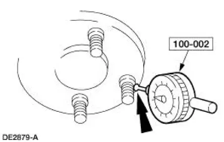
2. Rotate the hub or flange until the next bolt is contacted. Record the measurement and continue until each bolt is checked. The difference between the maximum and minimum contact readings will be the total wheel hub or axle flange bolt pattern runout. The runout must not exceed 0.38 mm (0.015 inch).
Pilot Runout
1. Position the special tools as close to the hub or axle flange face as possible. Zero the indicator to allow the pointer to deflect either way.
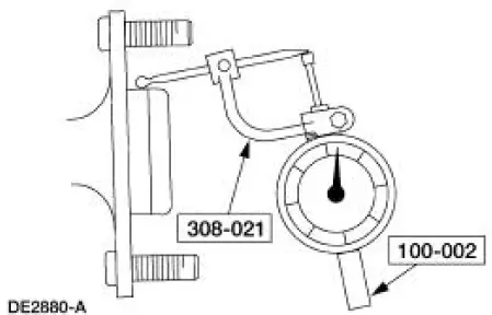
2. Rotate the hub or flange one full turn and note the maximum and minimum readings. The difference between the maximum and minimum readings will be the total pilot runout. Pilot runout must not exceed 0.15 mm (0.006 inch).
 Driveline Angle
Item
Description
1
Bottom of the frame
2
Engine crankshaft centerline
3
Engine angle
4
Driveshaft and coupling shaft centerline
5
Driveshaft an ...
 Wheel Hub or Axle Flange Face Runout
NOTE: If the axle shaft assembly is removed, check runout of the shaft
itself. The forged (unmachined)
part of the shaft is allowed to have as much as 3.0 mm (0.120 inch) runout. This
alone will not ...
Other materials:
Remote control
Integrated Keyhead Transmitters
The key blade is used to start the
vehicle and unlock or lock the
driver’s door from outside the
vehicle. The transmitter portion
functions as the remote control.
Note: If the vehicle is not equipped with active anti-theft sy ...
Exhaust Manifold to Exhaust Gas Recirculation (EGR)
Valve Tube - Cobra
Removal and Installation
1. Remove the EGR valve. For addditional information, refer to Exhaust
Gas Recirculation (EGR)
Valve-Cobra in this section.
2. With the vehicle in NEUTRAL, position it on a hoist.
3. Disconnect the exhaust manifold to EGR valve ...
Engine Coolant Temperature (ECT) Sensor - Cobra
Material
Item
Specification
Pipe Sealant with Teflon
D8AZ-19554-A
WSK-M2G350-A2
Removal and Installation
1. Partially drain the engine cooling system. For additional
information, refer to Section.
2. Disconnect the engine coolant te ...
