Ford Mustang (1999-2004) Service Manual: Transmission (Assembly)
Special Tool(s)
|
|
Dial Indicator with Bracketry 100-002 (TOOL-4201-C) or Equivalent |
|
|
Gauge, Clutch Housing 308-021 (T75L-4201-A) |
|
|
Extension Housing Seal Replacer 308-227 (T94P-7657-A) |
|
|
Holding Fixture 307-003 (T57L-500-B) |
|
|
Remover and Replacer Tube 308-052 (T77J-7025-B) |
|
|
Torrington Bearing Installer 308-083 (T83P-7025-AH) |
Material
| Item | Specification |
| Motorcraft MERCON Multi- Purpose (ATF) Transmission Fluid XT-2-QDX | MERCON |
| Pipe Sealant with Teflon D8AZ-19554-A | ESR-M18P7- A |
| Multi-Purpose Grease D0AZ-19554-AA | ESB-M1C93- B |
| Clear Silicone Rubber D6AZ-19562-AA | ESB-M4G92- A |
| Motorcraft Premium Long Life Grease XG-1-C | ESA-M1C75- B |
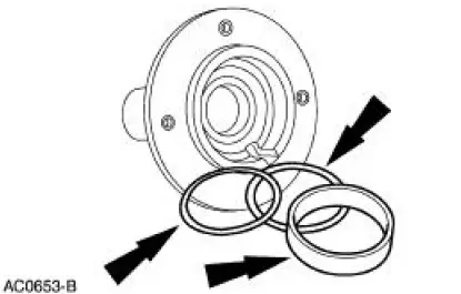
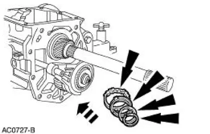
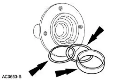
1. Soak the blocking rings in transmission fluid for ten minutes.
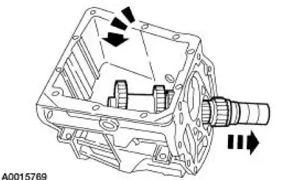
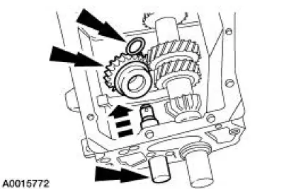
2. Position the countershaft cluster gear in the case.
3. CAUTION: Failure to correctly support the case during bearing installation will result in permanent distortion of the case.
Using a the special tools and a press, install the rear countershaft bearing assembly.
1. Position two 6.35 mm (0.25 in) pieces of bar stock between the countershaft and the case.
2. Using a the special tools and a press, install the rear countershaft bearing assembly.
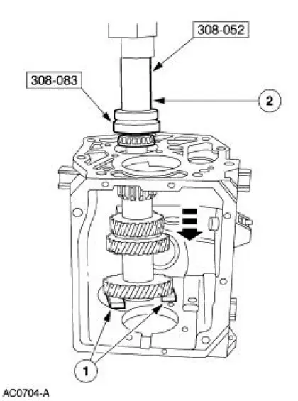
4. Install the rear countershaft bearing race.
5. NOTE: Do not install the shims at this time.
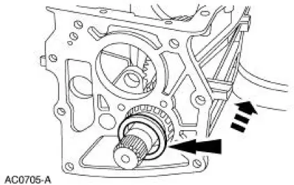
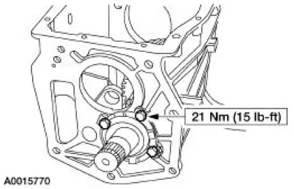
Install the countershaft rear bearing retainer.
6. Using the special tool, measure the countershaft cluster gear end play.
- If the end play is not within the specifications, remove the countershaft rear bearing retainer, and install the necessary thickness shim(s). Reinstall the countershaft rear bearing retainer, and recheck the end play.
- Bend the tabs of the countershaft rear bearing retainer over the bolts when the end play adjustment is complete.
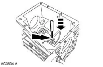
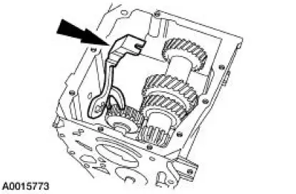
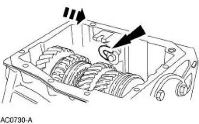
7. Position the reverse idler gear and bushing in the case with the shift lever groove facing the rear of the case. Install the reverse idler gear shaft and the reverse gear overtravel stop.
8. Install the pin.
9. Align the reverse gearshift lever, the reverse shift fork, and the reverse positioning spring.
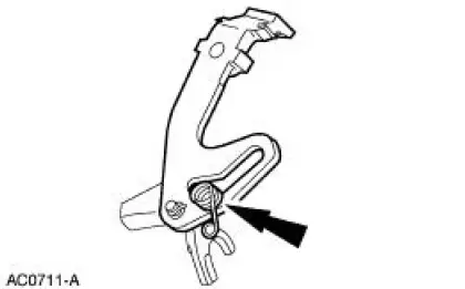
10. NOTE: Observe the reverse positioning spring rotation. The spring must rotate counterclockwise into its installed position.
Install the reverse shift fork.
- Place the reverse idler gear and bushing into the NEUTRAL position. Align the reverse shift fork and the reverse idler gear and bushing. Push downward on the reverse shift fork until fully engaged into the reverse idler gear and bushing.
11. Install the output shaft assembly.
12. NOTE: Position the looped end of the reverse positioning spring around the shift lever reverse pin.
Apply pipe sealant to the shift lever reverse pin threads and install the pin.
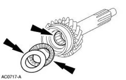
13. Install the roller bearings, the input shaft bearing spacer, the thrust bearing, and the thrust washer.
- Coat the 15 bearings, the spacer, the thrust bearing, and the thrust washer with grease.
14. NOTE: If not done so previously, soak the blocking ring in MERCON Multi-Purpose ATF Transmission Fluid XT-2-QDX or equivalent for ten minutes.
Install the fourth speed synchronizer blocking ring.
- Align the notches in the synchronizer blocking ring and the synchronizer hub inserts.
15. NOTE: Verify that the fourth speed synchronizer blocking ring is still in position.
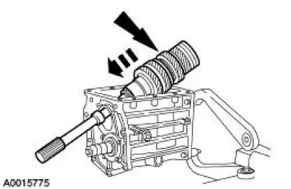
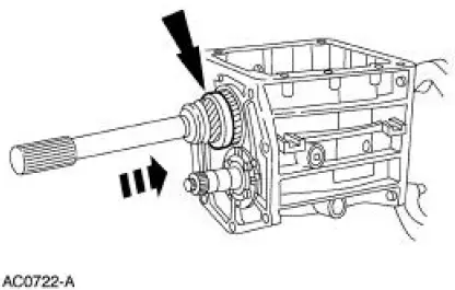
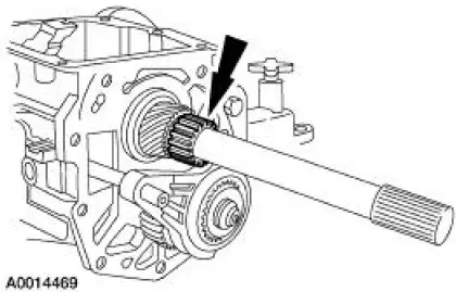
Align the flat on the fourth gear clutching teeth with the countershaft cluster gear and install the input shaft.
16. NOTE: Do not install the end play shims at this time.
NOTE: Do not apply sealant to the input shaft bearing retainer at this time.
Install the bearing race in the bearing retainer.
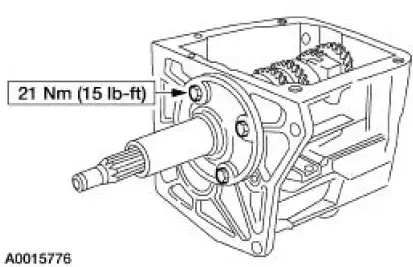
17. Install the input shaft bearing retainer with the notch facing upward.
18. Install the bolts.
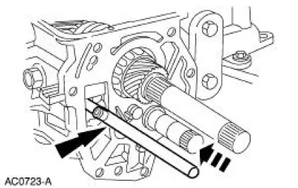
19. Install the output shaft rear bearing cup
20. Install the reverse gear shift rail.
- Align the ball stud with the slot in the case and align the reverse gear shift rail with the reverse shift fork. Once the ball stud enters the case, rotate the reverse gear shift rail until the ball aligns with the reverse gearshift lever. Rotate the reverse gear shift rail counterclockwise until the ball stud fully engages the reverse gearshift lever.
21. NOTE: If not done so previously, soak the blocking ring in transmission fluid for ten minutes.
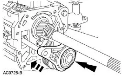
Install the fifth speed cluster gear, the synchronizer blocking ring, the synchronizer assembly, and the fifth gear shifter fork as an assembly.
22. CAUTION: To prevent component damage when installing the extension housing (7A039), the alignment tab on the reverse brake ring (7M000) must engage the alignment slot in the extension housing.
NOTE: If not done so previously, soak the blocking ring in transmission fluid for ten minutes.
Install the synchronizer blocking ring, the reverse brake ring, the thrust washer, and the fifth speed synchronizer retaining snap ring.
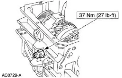
23. Apply pipe sealant to the reversing lamp switch threads and install the switch.
24. Install the reverse gearshift lever retaining clip.
25. Install the output shaft speed wheel and the snap ring.
26. CAUTION: Do not under any circumstance apply silicone sealant to the top of the transmission case. The sealant could fall into the transmission and affect transmission operation.
Apply a 3.2-mm (1/8-in) bead of silicone rubber to the sealing surface on the case cover.
27. NOTE: Verify that all of the synchronizers are in the NEUTRAL position and the gear shifter forks in the cover are in the NEUTRAL position.
Install the case cover.
- Position the cover toward the filler plug side of the transmission and lower it until the gear shifter forks engage the synchronizers. Continue to lower the cover and move it into position to engage the reverse gearshift lever.
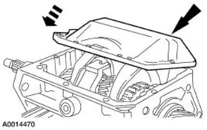
28. Install the bolts.
29. Apply a 3.2-mm (1/8-in) bead of silicone rubber to the sealing surface on the extension housing.
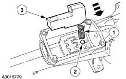
30. Install the detent ball, the shifter detent spring, and the gearshift offset lever.
1. Coat the shifter detent spring with petroleum jelly and install it in the gearshift offset lever.
2. Lubricate the detent plate and install the detent ball in the neutral position on the plate.
3. Position the gearshift offset lever in the extension housing with the gear shift interlock spring over the detent ball.
31. CAUTION: To prevent component damage, the alignment tab on the reverse brake ring must align with the alignment slot in the extension housing.
NOTE: Verify that the oil pick-up funnel engages the fifth gear synchronizer.
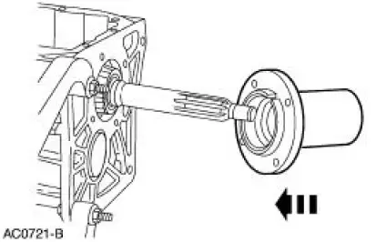
Slide the gearshift offset lever and the extension housing into place as an assembly. Press downward on the gearshift offset lever to compress the shifter interlock spring and push the gearshift offset lever and extension housing into place.
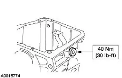
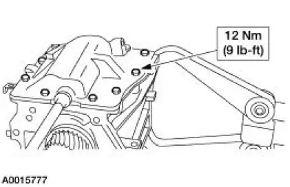
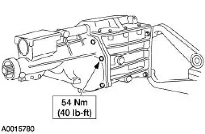
32. Install the identification tag and the bolts.
33. Install the split pin and the gearshift shaft bushing.
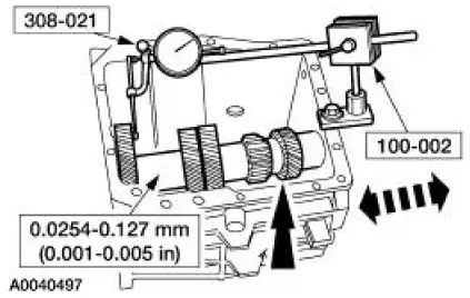
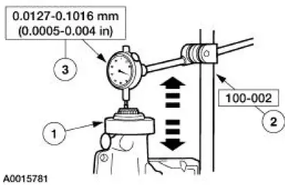
34. Using the special tools, measure the output shaft end play.
1. Place the transmission in a vertical position.
2. Install the special tool.
3. Push upward on the input shaft and record the dial indicator reading.
35. CAUTION: Install the thickest shim closest to the front bearing cup to provide support for the cup.
CAUTION: Although zero end play is the ideal, end play up to mm (0.002 in) is an acceptable tolerance. Do not overload the bearings with a shim that is too thick as damage may occur.
NOTE: Select a shim with a thickness equal to the dial indicator reading. This will provide zero end play.
Rotate the transmission to the horizontal position and remove the input shaft bearing retainer.
Remove the bearing race and install the necessary shim(s).
36. CAUTION: Do not cover the notch in the input shaft bearing retainer with sealer.
Apply a 3.2-mm (1/8-inch) bead of silicone rubber to the sealing surface on the input shaft bearing retainer.
37. Install the input shaft bearing retainer and the four bolts.
38. Apply a 3.2-mm (1/8-inch) bead of silicone rubber to the sealing surface on the gearshift lever.
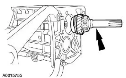
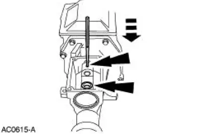
39. Install the gearshift lever.
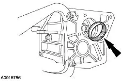
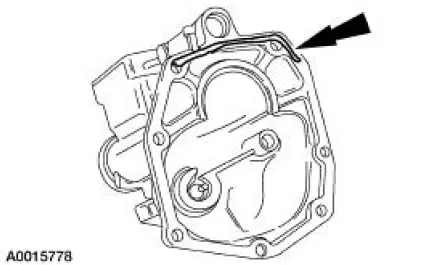
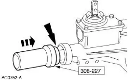
40. Using the special tool, install the extension housing fluid seal.
41. Install the case plug.
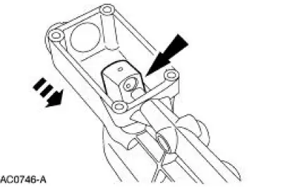
42. NOTE: Before installing the transmission, the ball stud, clutch release lever and the input shaft must be cleaned and lubricated with grease.
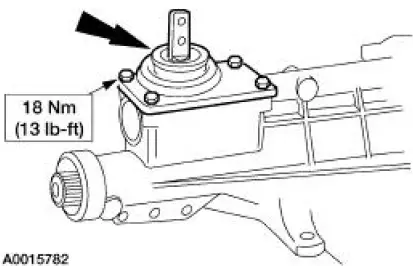
Install the clutch release hub and bearing and the clutch release lever.
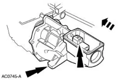
Transmission
1. NOTE: Before installing the transmission, the ball stud, clutch release lever and the input shaft must be cleaned and lubricated. Use Motorcraft Premium Long-Life Grease XG-1-C or XG-1-K or equivalent meeting Ford specification ESA-M1C75-B.
To install, reverse the removal procedure. Refer to Transmission in this section.
- Check, and as necessary, fill the transmission with MERCON Multi-Purpose ATF Transmission Fluid XT-2-QDX or equivalent. The total fill capacity is 2.6L (2.8 qt).
 Synchronizers
Disassembly
NOTE: This procedure applies to all synchronizer assemblies
(7124). The synchronizers are slightly
different in design. Notation is made where procedural differences occur.
1. On the ...
 Manual Transaxle/Transmission - TR3650
General Specifications
Torque Specifications
...
Other materials:
Hydraulic Lash Adjusters
Removal
1. Remove the roller followers. For additional information, refer to Roller
Followers in this section.
2. Remove the 16 hydraulic lash adjusters.
3. Inspect the roller followers. For additional information, refer to
Section.
Installation
1. To ins ...
Removal
WARNING: Do not smoke or carry lighted tobacco or open flame of any
type when
working on or near any fuel related components. Highly flammable mixtures are
always present
and may be ignited. Failure to follow these instructions may result in personal
injury ...
Instrument Panel and Console
Torque Specifications
Instrument Panel
The instrument panel consists of the following components:
instrument cluster
instrument panel finish panels
audio unit
A/C controls
glove compartment door
passenger air bag module
glove compart ...
