Ford Mustang (1999-2004) Service Manual: Arm - Lower
Removal
CAUTION: Suspension fasteners are critical parts because they affect performance of vital components and systems and their failure can result in major service expense. A new part with the same part number or an equivalent part must be installed, if installation is necessary. Do not use a part of lesser quality or substitute design. Torque values must be used as specified during reassembly to ensure correct retention of these parts.
1. Mark the front shock absorber (18124) relative to the protective sleeve with the vehicle in a static, level ground position (curb height).
2. Raise the vehicle on a hoist.
3. Remove the wheel and tire assembly.
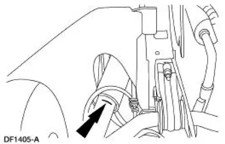
4. Remove the front brake disc shield.
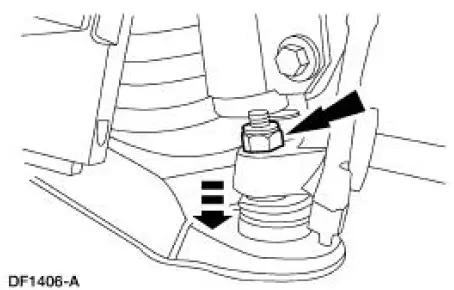
5. CAUTION: To prevent damage to the front suspension lower arm (3078) do not remove the nut from the ball joint (3050) at this time.
Disconnect the ball joint stud from the arm.
- Loosen the nut two or three turns.
- Sharply rap on the front wheel spindle (3105) at the ball joint connection to disconnect the ball joint stud.
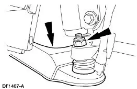
6. Remove the front coil spring (5310). For additional information, refer to Spring in this section.
7. Remove the nut and the front suspension lower control arm. Discard the nut.
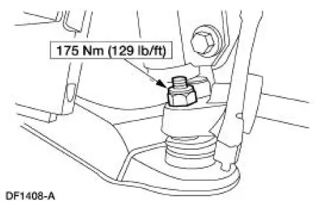
Installation
1. To install, reverse the removal procedure.
2. Check wheel alignment. Adjust if necessary.
 Wheel Hub and Bearing
Removal
CAUTION: Suspension fasteners are critical parts because they affect
performance of vital
components and systems and their failure can result in major service expense. A
new part with
the sa ...
 Bar - Stabilizer
Removal
CAUTION: Suspension fasteners are critical parts because they affect
performance of vital
components and systems and their failure can result in major service expense. A
new part with
the sa ...
Other materials:
Cylinder Head LH
Special Tool(s)
Remover, Power Steering
Pump Pulley
211-016 (T69L-10300-B)
Installer, Power Steering Pump
Pulley
211-009
Material
...
Reverse Clutch
Special Tool(s)
Dial Indicator Gauge with
Holding Fixture
100-002 (TOOL-4201-C)
Compressor, Clutch Spring
307-015 (T65L-77515-A)
Protector, Transmission
Reverse Clutch Outer Fluid
Seal
307-424
Protecto ...
Differential Case
Special Tool(s)
2-Jaw Puller
205-D072 (D97L-4221-A) or
equivalent
Dial Indicator Gauge with
Holding Fixture
100-002 (TOOL-4201-C) or
equivalent
Gauge, Clutch Housing
308-021 (T75L-4201-A) or
equivalent
Instal ...
