Ford Mustang (1999-2004) Service Manual: Hydro-Boost Bleeding
1. NOTE: The Hydro-Boost power brake booster (2B560) is generally self-bleeding, and the following procedure will normally bleed the air from the power brake booster. Normal operation of the vehicle will further remove any additional trapped air.
Fill the power steering oil reservoir (3A697) with MERCON Multi-Purpose ATF XT-2-QDX or MERCON equivalent.
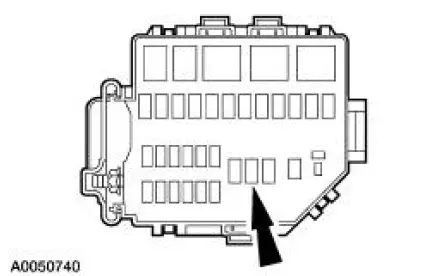
2. Remove the powertrain control module (PCM) fuse to prevent the engine from starting.
3. Crank the engine for several seconds.
4. Check the fluid level in the power steering oil reservoir and add if necessary. Install the powertrain control module (PCM) fuse.
5. Start the engine.
6. With the engine running, turn the steering wheel (3600) from stop-to-stop twice. Turn the engine off.
7. Depress the brake pedal (2455) several times to discharge the accumulator.
8. Repeat Steps 5 and 6.
9. If foaming occurs, stop the engine and allow the foam to dissipate.
10. Repeat Steps 5 and 6 as required, until all the air is removed from the system (when the foaming stops).
 Brake Booster - Hydro-Boost (Description and Operation)
The Hydro-Boost brake booster is a hydraulically operated brake booster
powered by the power
steering pump (3A674). The power steering pump provides the fluid pressure to
operate both the
power brak ...
 Brake Booster - Vacuum (Removal and Installation)
Removal
1. Disconnect the battery ground cable (14301).
2. Remove the air cleaner housing.
3. Remove the brake master cylinder nuts.
4. Position the brake master cylinder (2140) aside.
5. W ...
Other materials:
Inspection and Verification
CAUTION: Do not hold the steering wheel (3600) at the stops for an
extended amount of
time. Damage to the power steering pump (3A674) will result.
NOTE: Make the following preliminary checks before repairing the
steering system:
1. Verify the customer conce ...
Supply Manifold
Removal
WARNING: Do not smoke or carry lighted tobacco or open flame of any
type when
working on or near any fuel related components. Highly flammable mixtures are
always present
and can ignite. Failure to follow these instructions can result in personal
in ...
Brake Shift Interlock Actuator
Removal
1. Remove the shifter top control panel.
2. Disconnect the electrical connectors.
3. Remove the shifter bezel.
4. Remove the bulb from the bezel.
5. Disconnect the electrical connector.
6. CAUTION: Extra force may be needed to lift up on th ...
