Ford Mustang (1999-2004) Service Manual: Component Tests
Heater Core
WARNING: Carbon monoxide gas is colorless, odorless and dangerous. If it is necessary to operate the engine with the vehicle in a closed area such as a garage, always use an exhaust collector to vent the exhaust gases outside the closed area. Failure to follow these instructions may result in personal injury.
1. NOTE: Testing of returned heater cores reveals that a large percentage of heater cores are good and did not require installation of a new heater core. If a heater core leak is suspected, the heater core must be tested by following the Plugged Heater Core Component Test before the Heater Core Pressure Test. Carry out a system inspection by checking the heater system thoroughly as follows: Inspect for evidence of coolant leakage at the heater water hose to heater core attachments. A coolant leak in the heater water hose could follow the heater core tube to the heater core and appear as a leak in the heater core.
CAUTION: Spring-type clamps are installed as original equipment. Installation and overtightening of non-specification clamps can cause leakage at the heater water hose connection and damage the heater core.
2. Check the integrity of the heater water hose clamps.
Heater Core-Plugged
WARNING: The heater core inlet hose will become too hot to handle if the system is working correctly.
1. Check to see that the engine coolant is at the correct level.
2. Start the engine and turn on the heater.
3. When the engine coolant reaches operating temperature, feel the heater core outlet hose to see if it is hot.
If it is not hot:
- the heater core may have an air pocket.
- the heater core may be plugged.
- the thermostat is not working correctly.
Heater Core-Pressure Test
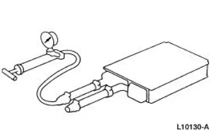
Use the radiator/heater core pressure tester to carry out the pressure test.
1. NOTE: Due to space limitations, a bench test may be necessary for pressure testing.
Drain the coolant from the cooling system. For additional information, refer to Section.
2. Disconnect the heater water hoses from the heater core. For additional information, refer to
3. Install a short piece of heater water hose, approximately 101 mm (4 inches) long on each heater core tube.
4. Fill the heater core and heater water hoses with water and install Plug BT-7422-B and adapter BT-7422-A from the radiator/heater core pressure tester in the heater water hose ends. Secure the heater water hoses, plug and adapter with hose clamps.
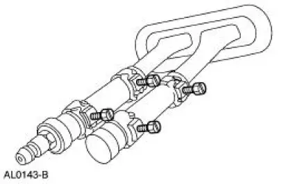
5. Attach the pump and gauge assembly from the radiator/heater core pressure tester to the adapter.
6. Close the bleed valve at the base of the gauge. Pump 241 kPa (35 psi) of air pressure into the heater core.
7. Observe the pressure gauge for a minimum of three minutes.
8. If the pressure drops, check the heater water hose connections to the core tubes for leaks. If the heater water hoses do not leak, remove the heater core from the vehicle and carry out the bench test.
Heater Core-Bench Test
1. Remove the heater core from the vehicle. For additional information, refer to Section.
2. Drain all of the coolant from the heater core.
3. Connect the 101 mm (4 inch) test heater water hoses with plug and adapter to the core tubes.
Then connect the radiator/heater core pressure tester to the adapter.
4. Apply 241 kPa (35 psi) of air pressure to the heater core. Submerge the heater core in water.
5. If a leak is observed, install a new heater core.
A/C Evaporator/Condenser Core-On-Vehicle Leak Test
1. Discharge and recover the refrigerant. For additional information, refer to Air Conditioning (A/C) System Recovery, Evacuation and Charging in this section.
2. NOTE: DO NOT leak test an A/C evaporator core with the suction accumulator/drier (19C836) attached to the core tubes.
Disconnect the suspect A/C evaporator core or A/C condenser core from the A/C system. For additional information, refer to Section.
3. Clean the spring lock couplings. For additional information, refer to Spring Lock Coupling in this section.
4. Connect the appropriate test fittings from the A/C Test Fitting Set to the evaporator or condenser tube connections.
5. NOTE: The automatic shut-off valves on some gauge set hoses do not open when connected to the test fittings. If available, use hoses without shut-off valves. If hoses with shut-off valves are used, make sure the valve opens when attached to the test fittings or install an adapter which will activate the valve. The test is not valid if the shut-off valve does not open.
Connect the red and blue hoses from the manifold gauge set to the test fittings on the A/C evaporator core or A/C condenser core. Connect the yellow hose to a known good vacuum pump.
6. Open both gauge set valves and start the vacuum pump. Allow the vacuum pump to operate for a minimum of 45 minutes after the gauge set low pressure gauge indicates 101 kPa (30 in-Hg).
The 45-minute evacuation is necessary to remove any refrigerant from oil left in the A/C evaporator core or A/C condenser core. If the refrigerant is not completely removed from the oil, outgassing will degrade the vacuum and appear as a refrigerant leak.
7. If the low pressure gauge reading will not drop to 101 kPa (30 in-Hg) when the valves on the gauge and manifold set are open and the vacuum pump is operating, close the gauge set valves and observe the low pressure gauge. If the pressure rises rapidly to zero, a large leak is indicated. Recheck the test fitting connections and gauge set connections before installing a new A/C evaporator core or A/C condenser core.
8. After evacuating for 45 minutes, close the gauge set valves and stop the vacuum pump.
Observe the low pressure gauge; it should remain at the 101 kPa (30 in-Hg) mark.
- If the low pressure gauge reading rises 34 or more kPa (10 or more in-Hg) of vacuum from the 101 kPa (30 in-Hg) position in 10 minutes, a leak is indicated.
- If a very small leak is suspected, wait 30 minutes and observe the vacuum gauge.
- If a small amount of vacuum is lost, operate the vacuum pump with gauge valves open for an additional 30 minutes to remove any remaining refrigerant from the oil in the A/C evaporator core or A/C condenser core. Then recheck for loss of vacuum.
- If a very small leak is suspected, allow the system to sit overnight with vacuum applied and check for vacuum loss.
9. If the A/C evaporator core or A/C condenser core does leak, as verified by the above procedure, install a new A/C evaporator core or A/C condenser core.
A/C Compressor-External Leak Test
1. Install the A/C pressure test adapter on the rear head of the A/C compressor using the existing manifold retaining bolt.
2. Connect the high and low pressure lines of a manifold gauge set or a refrigerant recovery/recycling station such as the R-134a A/C Service Center to the corresponding fittings on the A/C pressure test adapter.
3. Attach the center hose of the manifold gauge set to a refrigerant container standing in an upright position.
4. Hand-rotate the compressor shaft 10 complete revolutions to distribute the oil inside the A/C compressor.
5. Open the low pressure gauge valve, the high pressure gauge valve and the valve on the refrigerant container to allow the refrigerant vapor to flow into the A/C compressor.
6. Using the Refrigerant Leak Detector, check for leaks at the compressor shaft seal and the compressor center seal.
7. If a shaft seal leak is found, install a new shaft seal. For additional information, refer to Section. If an external leak is found at the center joint of the A/C compressor, install a new A/C compressor.
8. When the leak test is complete, recover the refrigerant. For additional information, refer to Air Conditioning (A/C) System Recovery, Evacuation and Charging in this section.
 Pinpoint Tests
PINPOINT TEST P1464: DTC P1464: A/C DEMAND OUT OF SELFTEST
RANGE
Test Step
Result / Action to Take
P14641 RECHECK FOR THE DTC
YesGO to P14642 .
No
The system is functioning
correc ...
 Air Conditioning (A/C) System Check - Retail Procedure
NOTE: This Retail Procedure is not eligible for claiming on Ford
paid repairs (warranty and ESP).
NOTE: The engine should be run at idle for 10 minutes with the air
conditioning on and set to MA ...
Other materials:
Pinpoint Test N: DTC B1869 - Air Bag Indicator Inoperative
Normal Operation
The air bag indicator is designed to illuminate for 6 (+/-2) seconds when
the ignition switch is turned to
the RUN position. This initial 6 seconds of illumination is considered
normal operation and is called
proveout of the air bag ind ...
Road Test
NOTE: It may be necessary to have the customer ride along or drive the
vehicle to point out the
concern. During the road test, take into consideration the customer's driving
habits and the driving
conditions. The customer's concern just may be an acceptable ...
Rear-view camera system
WARNING: The rear view camera system is a reverse aid
supplement device that still requires the driver to use it in
conjunction with the interior and exterior mirrors for maximum
coverage.
WARNING: Objects that are close to either corner of the
bumper or under ...
