Ford Mustang (1999-2004) Service Manual: Component Tests
Idle Air Control (IAC) Valve
1. Open the hood.
2. NOTE: Key symptom is elevated idle speed while noise is occurring.
NOTE: "Snapping" the throttle can induce the noise.
Verify the condition by operating the vehicle for a short time.
3. Inspect the IAC valve. If physical evidence of contamination exists, install a new IAC valve.
4. While the noise is occurring, either place an EngineEAR probe near the IAC valve and the inlet tube, or create a 6.35 mm (0.25 in)-12.7 mm (0.50 in) air gap between the inlet tube and the clean air tube. If the IAC valve is making the noise, install a new IAC valve.
5. Test the vehicle for normal operation.
Steering Gear Grunt/Shudder Test
1. Start and run the vehicle to operating temperature.
2. Set engine idle speed to 1200 rpm.
3. CAUTION: Do not hold the steering wheel against the stops for more than three to five seconds at a time. Damage to the power steering pump will occur.
Rotate the steering wheel to the RH stop, then turn the steering wheel 90 back from that position. Turn the steering wheel slowly in a 15 to 30 arc.
4. Turn the steering wheel another 90. Turn the steering wheel slowly in a 15 to 30 arc.
5. Repeat the test with power steering fluid at different temperatures.
6. If a light grunt is heard or a low (50-200 Hz) shudder is present, this is a normal steering system condition.
7. If a loud grunt is heard, or a strong shudder is felt, fill and purge the power steering system.
Checking Tooth Contact Pattern and Condition of the Ring and Pinion
There are two basic types of conditions that will produce ring and pinion noise. The first type is a howl or chuckle produced by broken, cracked, chipped, scored or forcibly damaged gear teeth and is usually quite audible over the entire speed range. The second type of ring and pinion noise pertains to the mesh pattern of the gear pattern. This gear noise can be recognized as it produces a cycling pitch or whine. Ring and pinion noise tends to peak in a narrow speed range or ranges, and will tend to remain constant in pitch.
1. Raise and support the vehicle. For additional information.
2. Drain the axle lubricant.
3. Remove the carrier assembly or the axle housing cover depending on the axle type.
4. Inspect the gear set for scoring or damage.
5. In the following steps, the movement of the contact pattern along the length is indicated as toward the" heel" or "toe" of the differential ring gear.
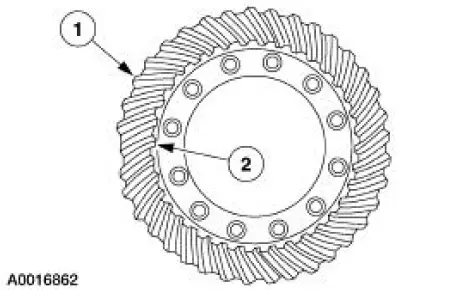
| Item | Description |
| 1 | Heel |
| 2 | Toe |
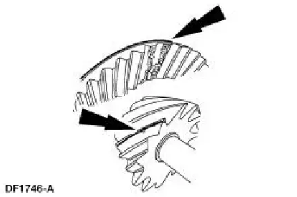
6. Apply a marking compound to a third of the gear teeth on the differential ring gear. Rotate the differential ring gear several complete turns in both directions until a good, clear tooth pattern is obtained. Inspect the contact patterns on the ring gear teeth.
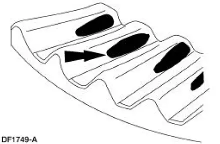
7. A good contact pattern should be centered on the tooth. It can also be slightly toward the toe.
There should always be some clearance between the contact pattern and the top of the tooth.
- Tooth contact pattern shown on the drive side of the gear teeth.
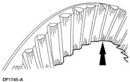
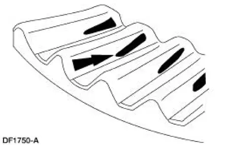
8. A high, thick contact pattern that is worn more toward the toe.
- Tooth contact pattern shown on the drive side of the gear teeth.
- The high contact pattern indicates that the drive pinion is not installed deep enough into the carrier.
- The differential ring gear backlash is correct, a thinner drive pinion shim is needed. A decrease will move the drive pinion toward the differential ring gear.
9. A high, thin contact pattern that is worn toward the toe.
- Tooth contact pattern shown on the drive side of the gear teeth.
- The drive pinion depth is correct. Increase the differential ring gear backlash.
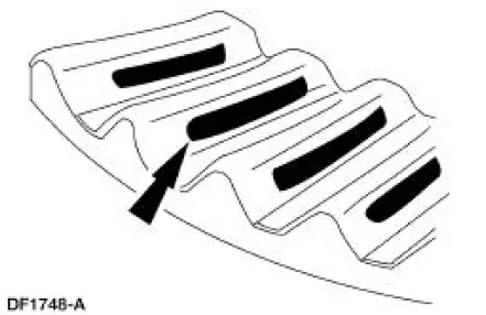
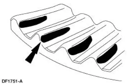
10. A contact pattern that is worn in the center of the differential ring gear tooth toward the heel.
- Tooth contact pattern shown on the drive side of the gear teeth.
- The low contact pattern indicates that the drive pinion is installed too deep into the carrier.
- The differential ring gear backlash is correct. A thicker drive pinion shim is needed.
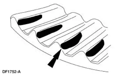
11. A contact pattern that is worn at the top of the differential ring gear tooth toward the heel.
- Tooth contact pattern shown on the drive side of the gear teeth.
- The pinion gear depth is correct. Decrease the differential ring gear backlash.
Tire Wear Patterns and frequency calculations
 Pinpoint Tests
The pinpoint tests are a step-by-step diagnostic process designed to
determine the cause of a condition. It may not always be necessary to follow a
pinpoint test to its conclusion. Carry out only th ...
 Tire Wear Chart
Wheel and tire NVH concerns are directly related to vehicle speed and are not
generally affected by
acceleration, coasting or decelerating. Also, out-of-balance wheel and tires can
vibrate at more ...
Other materials:
Ignition Coil
Material
Item
Specification
Silicone Brake Caliper Grease
and Dielectric Compound
D7AZ-19A331-A or equivalent
ESE-M1C171-
A
Removal and Installation
1. Disconnect the battery ground cable (14301). For additional
information, refer to ...
Supercharger Belt Idler Pulley
Removal and Installation
1. Remove the supercharger drive belt cover.
2. Rotate the supercharger belt tensioner clockwise and remove the
supercharger belt.
3. Remove the bolt and the supercharger belt idler pulley.
4. To install, reverse the removal pro ...
Relay Switch
1. Disconnect the battery ground cable. For additional information, refer
to Section.
2. Remove the power distribution box cover.
3. Remove the starter relay from the power distribution box.
Installation
1. To install, reverse the removal procedure. ...
