The pinpoint tests are a step-by-step diagnostic process designed to
determine the cause of a condition. It may not always be necessary to follow a
pinpoint test to its conclusion. Carry out only the
steps necessary to correct the condition. Then, test the system for normal
operation. Sometimes, it is
necessary to remove various vehicle components to gain access to the component
requiring testing.
Reinstall all components after verifying system operation is normal.
PINPOINT TEST A: BRAKE VIBRATION/SHUDDER
| Test Step |
Result / Action to Take |
| A1 ROAD TEST THE VEHICLE-LIGHT BRAKING |
Yes GO to A4 .
No
GO to A2 . |
|
|
| A2 ROAD TEST THE VEHICLE-MODERATE TO HEAVY
BRAKING |
Yes For vehicles with ABS,
GO to A3 . For vehicles
with standard brakes,
GO to A4 .
No
Vehicle is OK. VERIFY
condition with customer.
TEST the vehicle for
normal operation. |
- Road test the vehicle. At highway speeds of 89-97 km/h (55-60
mph), apply the brake using a moderate to heavy pedal force.
- Is there a vibration/shudder?
|
| A3 NORMAL ACTUATION OF THE ABS SYSTEM DIAGNOSIS |
Yes GO to A5 .
No
The brake system is
operating correctly. |
- During moderate to heavy braking, noise from the hydraulic
control unit (HCU) and pulsation in the brake pedal can be
observed. Pedal pulsation coupled with noise during heavy
braking or on loose gravel, bumps, wet or snowy surfaces is
acceptable and indicates correct functioning of the ABS
system. Pedal pulsation or steering wheel nibble, (frequency is
proportioned to the vehicle speed) indicates a concern with a
brake or suspension component.
- Is the vibration/shudder vehicle speed sensitive?
|
| A4 APPLICATION OF THE PARKING BRAKE |
Yes GO to A7 .
No
GO to A5 . |
- NOTE: Begin at the front of the vehicle unless the
vibration or
shudder has been isolated to the rear.
- This test is not applicable to vehicles with drum-in-hat type
parking brakes. For vehicles with drum-in-hat parking brakes,
proceed to the next test. For all other vehicles, apply the
parking brake to identify if the problem is in the front or rear
brake. At highway speeds of 89-97 km/h (55-60 mph), lightly
apply the parking brake until the vehicle slows down. Release
the parking brake immediately after the test.
- Is there a vibration/shudder?
|
| A5 CHECK THE FRONT WHEEL BEARINGS |
Yes GO to A6 .
No
INSPECT the wheel
bearings. ADJUST or
REPAIR as necessary.
TEST the system for
normal operation. |
- Check the front wheel bearings. Refer to Wheel Bearing Check
in this section.
- Are the wheel bearings OK?
|
| A6 CHECK THE FRONT SUSPENSION |
Yes GO to A7 .
No
REPAIR or INSTALL
new components as
necessary. TEST the
system for normal
operation. |
- Check the front suspension for:
- Broken or loose bolts.
- Damaged springs.
- Worn or damaged upper and lower control arm
bushings.
- Loose or rough front bearings.
- Uneven tire wear.
- Are all the suspension components in satisfactory
condition?
|
| A7 RESURFACE THE FRONT BRAKE DISCS |
Yes GO to A8 .
No
Vehicle is OK. |
- CAUTION: Do not use a bench lathe to machine brake
discs.
- NOTE: Follow the manufacturer's instructions to machine
the
brake discs. After machining, make sure the brake disc meets
the thickness specification.
- Refer to Brake Disc Machining in this section. Resurface the
front brake discs. Road test the vehicle.
- Is the vibration/shudder present?
|
| A8 CHECK THE REAR SUSPENSION |
Yes GO to A9 .
No
REPAIR or INSTALL
new components as
necessary. TEST the
system for normal
operation. |
- Check the rear suspension for:
- Broken or loose bolts.
- Damaged or worn springs or spring bushings.
- Worn or damaged upper and lower control arm
bushings.
- Worn or damaged trailing arms.
- Loose or rough rear bearings.
- Uneven tire wear.
- Are all the suspension components in satisfactory
condition?
|
| A9 RESURFACE THE REAR BRAKE DISC OR DRUM |
Yes CHECK the front
suspension for wear or
damage. RESURFACE
the front brake discs.
TEST the system for
normal operation.
No
Vehicle is OK. |
- CAUTION: Do not use a bench lathe to machine brake
discs.
- NOTE: Follow the manufacturers instructions to machine
the
brake discs. After machining, make sure the brake disc meets
the thickness specification.
- Refer to Brake Disc Machining in this section. Resurface the
rear brake discs or drums. Road test the vehicle.
- Is the vibration/shudder present?
|
PINPOINT TEST B: ENGINE TICKING NOISE
| Test Step |
Result / Action to Take |
| B1 CHECK FOR TICKING NOISE AT THE FUEL
RAIL |
Yes CHECK for TSB for applicable vehicle.
REPAIR as necessary. TEST the system
for normal operation.
No
GO to B2 . |
- Disconnect the first fuel line clip.
- Is the ticking noise gone?
|
| B2 CHECK FOR TICKING NOISE AT THE FUEL
INJECTOR |
Yes INSTALL a new fuel injector.
No
GO to B3 . |
|
|
| B3 CHECK THE BELT TENSIONER FOR TICKING
NOISE |
Yes INSTALL a new belt tensioner. TEST the
system for normal operation.
No
GO to B4 . |
- Inspect the accessory drive. Check for the belt
tensioner bottoming at end of travel or not at
end of stroke.
- Using an EngineEAR, listen at the belt
tensioner.
- Is the belt tensioner the source of the
noise?
|
| B4 CHECK THE WATER PUMP FOR TICKING
NOISE |
Yes INSTALL a new water pump. TEST the system for
normal operation.
No
GO to B5 . |
- Using an EngineEAR, listen at the water pump
for ticking noise.
- Is the water pump the source of the noise?
|
| B5 CHECK FOR AN OBSTRUCTION OF THE
COOLING FAN |
Yes REPAIR or INSTALL a new cooling fan.
TEST the
system for normal operation.
No
GO to B6 . |
- Inspect the cooling fan for obstructions.
- Check the cooling fan and shroud for wear or
damage.
- Was there an obstruction or does the
cooling fan show signs of damage?
|
| B6 CHECK THE OIL PUMP FOR TICKING NOISE |
Yes INSTALL a new oil pump. TEST the system for normal
operation.
No
GO to B7 . |
- Check the oil pump using EngineEARs and
probe at the oil filter adapter to verify the oil
pump as a source.
- Is the oil pump the source of the noise?
|
| B7 CHECK VALVE LIFTERS OR LASH
ADJUSTERS FOR CORRECT OPERATION |
Yes VERIFY customer concern. CONDUCT a
diagnosis of other suspect components.
No
INSTALL a new valve lifter/lash adjuster
(s). TEST the system for normal
operation. |
- Check valve lifter/lash adjuster for correct
operation, using EngineEARs.
- Are the valve lifters/lash adjusters operating correctly?
|
PINPOINT TEST C: ACCESSORY DRIVE BEARING HOOT
| Test Step |
Result / Action to Take |
| C1 CHECK THE IDLER AND TENSIONER
PULLEY BEARINGS |
Yes INSTALL a new pulley/idler. CARRY OUT the
Vehicle Cold Soak Procedure and TEST the
system for normal operation.
No
CONDUCT a diagnosis on other suspect
accessory drive components. |
- Carry out the Vehicle Cold Soak
Procedure in this section.
- Key in START position.
- Place an EngineEAR probe directly on the
pulley center post or bolt to verify which
bearing is making the noise.
- Key in OFF position.
- Is either bearing making the noise?
|
PINPOINT TEST D: POWER STEERING MOAN
| Test Step |
Result / Action to Take |
| D1 CHECK THE POWER STEERING
SYSTEM |
Yes GO to D2 .
No
CONDUCT a diagnosis on other suspect
accessory drive components. |
- Carry out the Vehicle Cold Soak
Procedure in this section.
- Key in START position.
- Turn the steering wheel while the noise
is occurring and listen for changes in
sound pitch or loudness.
- Key in OFF position.
- Does the sound pitch or loudness
change while turning the steering
wheel?
|
| D2 VERIFY THE SOURCE |
Yes VERIFY that the supply tube to the pump is
unobstructed. CHECK the fluid condition and
level. DRAIN the fluid and REFILL. CARRY
OUT the Vehicle Cold Soak Procedure and
TEST the system for normal operation.
No
Normal system operation. |
- Key in START position.
- Place an EngineEAR probe near the
power steering pump/reservoir while the
noise is occurring. While an assistant
turns the steering wheel, listen for
changes in sound pitch or loudness.
- Key in OFF position.
- Does the sound pitch or loudness
change while turning the steering
wheel?
|
PINPOINT TEST E: ENGINE DRIVEN COOLING FAN MOAN
| Test Step |
Result / Action to Take |
| E1 CHECK THE ENGINE DRIVEN COOLING
FAN AFTER A COLD SOAK |
Yes TEST the fan for normal operation. If the
fan tests normal, GO to E2 . Otherwise,
REPAIR as necessary.
No
Normal system operation. |
- Carry out the Vehicle Cold Soak Procedure
in this section.
- Key in START position.
- Assess the airflow.
- Raise the engine speed to 1500 rpm while
listening for the moan to increase in
proportion to the airflow.
- Key in OFF position.
- Does the moan increase in proportion to
the airflow?
|
| E2 CHECK THE ENGINE DRIVEN COOLING
FAN AT NORMAL OPERATING TEMPERATURE |
Yes Normal clutch operation.
No
INSTALL a new fan clutch. TEST the
system for normal operation. |
- Key in START position.
- Run the engine to normal operating
temperature while listening for the moan to
stop.
- Key in OFF position.
- Does the moan stop?
|
PINPOINT TEST F: DRUMMING NOISE
| Test Step |
Result / Action to Take |
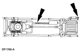
| F1 CHECK THE EXHAUST SYSTEM |
Yes CARRY OUT Exhaust
System Neutralizing in this
section. TEST the system
for normal operation.
No
GO to F2 . |
- Key in START position.
- Increase the engine rpm until the noise is the loudest. Note
the engine rpm.
- Key in OFF position.
- Add approximately 9 kg (20 lb) of weight to the exhaust
system. First place the weight at the tail pipe and test, then
at the front pipe.

|
| F2 POWERTRAIN/DRIVETRAIN MOUNT NEUTRALIZING |
Yes Vehicle OK. TEST the
system for normal
operation.
No
CONDUCT diagnosis of
other suspect components. |
- Carry out Powertrain/Drivetrain Mount Neutralizing in this
section. Test the system for normal operation.
- Is the noise reduced or eliminated?
|
PINPOINT TEST G: ENGINE TICKING, KNOCKING OR CONTINUOUS
RATTLE
| Test Step |
Result / Action to Take |
| G1 CHECK FOR NOISE AT THE VALVE COVERS
AND THE FRONT COVERS (OHC ENGINES) |
Yes REMOVE the appropriate cover and
INSPECT for loose, worn/broken
components. REPAIR as necessary.
TEST the system for normal operation.
No
GO to G2 . |
- Carry out the Vehicle Cold Soak Procedure in
this section.
- Key in START position.
- NOTE: For a short-duration ticking noise,
multiple engine starts may be necessary.
- Using an EngineEAR, listen closely at the valve
covers and the front covers (OHC engines) by
placing the probe near the surface of the valve
cover and then on the surface front cover.
- Key in OFF position.
- Is the noise source apparent?
|
| G2 CHECK FOR NOISE AT THE CYLINDER
BLOCK |
Yes REPAIR or INSTALL new components
as necessary.
No
GO to G3 . |
- Key in START position.
- Using an EngineEAR, listen closely at the
cylinder block by placing a probe on or near
each freeze plug.
- Key in OFF position.
- Is the noise source apparent?
|
| G3 CHECK FOR NOISE WHILE DISCONNECTING
EACH FUEL INJECTOR ELECTRICAL
CONNECTOR, ONE AT A TIME |
Yes INSTALL a new fuel injector. TEST the
system for normal operation.
No
INSPECT accessory drive system or the
transmission as a possible source. |
- Key in START position.
- Disconnect each fuel injector electrical
connector, one at a time, to decrease piston
force and listen for the noise.
- Key in OFF position.
- Is the noise reduced or eliminated?
|
PINPOINT TEST H: FRONT SUSPENSION NOISE
| Test Step |
Result / Action to Take |
| H1 ROAD TEST THE VEHICLE |
Yes GO to H2 .
No
The suspension system is
OK. CONDUCT a diagnosis
on other suspect systems. |
|
|
| H2 INSPECT THE STEERING SYSTEM |
Yes REPAIR the steering
system. INSTALL new
components as necessary.
TEST the system for normal
operation.
No
GO to H3 . |
- WARNING: The electrical power to the air
suspension system must be shut off prior to hoisting,
jacking or towing an air suspension vehicle. This can
be accomplished by turning off the air suspension
switch. Failure to do so can result in unexpected
inflation or deflation of the air springs, which can result
in shifting of the vehicle during these operations.
- Raise and support the vehicle.
- Check the steering system for wear or damage. Carry out a
steering linkage test.
- Inspect the tire wear pattern. Refer to Tire Wear Patterns
chart in this section.
- Are the steering components worn or damaged?
|
| H3 FRONT SHOCK ABSORBER/STRUT CHECK |
Yes TIGHTEN to specifications if
loose. INSTALL new front
shock absorbers/struts if
damaged. TEST the system
for normal operation.
No
GO to H4 . |
|
|
| H4 CHECK THE FRONT SPRINGS |
Yes REPAIR or INSTALL new
components as necessary.
TEST the system for normal
operation.
No
GO to H5 . |
- Check the front spring and front spring mounts/brackets for
wear or damage.
- Are the front springs or spring mounts/brackets worn
or damaged?
|
| H5 CHECK THE CONTROL ARMS/RADIUS ARMS |
Yes REPAIR or INSTALL new
components as necessary.
TEST the system for normal
operation.
No
GO to H6 . |
- Inspect the control arm bushings for wear or damage.
- Inspect for twisted or bent control/radius arm.
- Are the control/radius arms damaged or worn?
|
| H6 CHECK THE STABILIZER BAR/TRACK BAR |
Yes REPAIR or INSTALL new
components as necessary.
TEST the system for normal
operation.
No
Suspension system OK.
CONDUCT diagnosis on
other suspect systems. |
- Check the stabilizer bar/track bar bushings and links for
damage or wear.
- Check the stabilizer bar/track bar for damage.
- Check for loose or damaged stabilizer bar isolators or
brackets.
- Are the stabilizer bar/track bar components loose, worn
or damaged?
|
PINPOINT TEST I: REAR SUSPENSION NOISE
| Test Step |
Result / Action to Take |
| I1 ROAD TEST THE VEHICLE |
Yes GO to I2 .
No
The suspension system is
OK. Conduct a diagnosis on
other suspect systems |
|
|
| I2 REAR SHOCK ABSORBER/STRUT CHECK |
Yes TIGHTEN to specifications if
loose. INSTALL new rear
shock absorbers/struts if
damaged. TEST the system
for normal operation.
No
GO to I3 . |
- WARNING: The electrical power to the air
suspension system must be shut off prior to hoisting,
jacking or towing an air suspension vehicle. This can
be accomplished by turning off the air suspension
switch. Failure to do so can result in unexpected
inflation or deflation of the air springs, which can result
in shifting of the vehicle during these operations.
- Raise and support the vehicle.
- Check the rear shock absorber/strut mounts for loose bolts
or nuts.
- Check the rear shock absorbers/struts for damage. Carry
out a shock absorber check.
- Are the rear shock absorbers/struts loose or damaged?
|
| I3 CHECK THE REAR SPRINGS |
Yes REPAIR or INSTALL new
components as necessary.
TEST the system for normal
operation.
No
GO to I4 . |
- Check the rear springs and rear spring mounts/brackets for
wear or damage.
- Are the rear springs or spring mounts/brackets worn or
damaged?
|
| I4 CHECK THE CONTROL ARMS/TRAILING ARMS |
Yes REPAIR or INSTALL new
components as necessary.
TEST the system for normal
operation.
No
GO to I5 . |
- Inspect the control arm/trailing arm bushings for wear or
damage. Check for loose control arm/trailing arm bolts.
- Inspect for twisted or bent control arm/trailing arms.
- Are the control arm/trailing arms loose, damaged or
worn?
|
| I5 CHECK THE STABILIZER BAR/TRACK BAR |
Yes REPAIR or INSTALL new
components as necessary.
TEST the system for normal
operation.
No
Suspension system OK.
CONDUCT diagnosis on
other suspect systems. |
- Check the stabilizer bar/track bar bushings and links for
damage or wear.
- Check the stabilizer bar/track bar for damage.
- Check for loose or damaged stabilizer bar isolators or
brackets.
- Are the stabilizer bar/track bar components loose, worn
or damaged?
|
PINPOINT TEST J: WHEEL AND TIRE
| Test Step |
Result / Action to Take |
| J1 ROAD TEST THE VEHICLE |
Yes GO to J2 .
No
The wheel and tires
are OK. CONDUCT a
diagnosis on other
suspect systems. |
- NOTE: Wheel or tire vibrations felt in the steering wheel
are most
likely related to the front wheel or tire. Vibration felt through
the
seat are most likely related to the rear wheel or tire. This may not
always be true, but it can help to isolate the problem to the front
or rear of the vehicle.
- Test drive the vehicle at different speed ranges.
- During the road test, if the vibration can be eliminated by
placing
the vehicle in neutral or is affected by the speed of the engine,
the cause is not the wheels or tires.
- Is there a vibration and noise?
|
| J2 CHECK THE FRONT WHEEL BEARINGS |
Yes GO to J3 .
No
INSPECT the wheel
bearings. ADJUST or
REPAIR as necessary.
TEST the system for
normal operation. |
- Check the front wheel bearings. Refer to Wheel Bearing Check in
this section.
- Are the wheel bearings OK?
|
| J3 INSPECT THE TIRES |
Yes CORRECT the
condition that caused
the abnormal wear.
INSTALL new tire(s).
TEST the system for
normal operation.
No
GO to J4 . |
- Check the tires for missing weights.
- Check the wheels for damage.
- Inspect the tire wear pattern. Refer to the Tire Wear Patterns
chart in this section.
- Do the tires have an abnormal wear pattern?
|
| J4 TIRE ROTATION |
Yes GO to J5 .
No
CHECK the wheel and
tire balance.
CORRECT as
necessary. TEST the
system for normal
operation. |
- Spin the tires slowly and watch for signs of lateral runout.

- Spin the tires slowly and watch for signs of radial runout.

- Are there signs of visual runout?
|
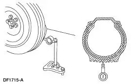
| J5 RADIAL RUNOUT CHECK ON THE TIRE |
Yes GO to J8 .
No
GO to J6 |
- Measure the radial runout of the wheel and tire assembly. A
typical specification for total radial runout is 0.045 inch.

- Is the radial runout within specifications?
|
| J6 RADIAL RUNOUT CHECK ON THE WHEEL |
Yes INSTALL a new tire.
TEST the system for
normal operation.
No
GO to J7 . |
- Measure the radial runout of the wheel. A typical specification
for
total radial runout is 0.045 inch.
- Is the radial runout within specifications?
|
| J7 CHECK THE HUB/BRAKE DISC OR DRUM PILOT RUNOUT OR
BOLT CIRCLE RUNOUT |
Yes INSTALL a new wheel.
TEST the system for
normal operation.
No
REPAIR or INSTALL
new components as
necessary. |
- Measure the pilot or bolt circle runout. A typical specification
for
radial runout is:
- Pilot runout- less than 0.15 mm (0.006 inch).
- Bolt circle runout- less than 0.38 mm (0.015 inch).
- Is the radial runout within specifications?
|
| J8 LATERAL RUNOUT CHECK ON THE TIRE |
Yes Wheel and tires OK.
CONDUCT diagnosis
on other suspect
systems.
No
GO to J9 . |
- Measure the lateral runout of the wheel and tire assembly. A
typical specification for total lateral runout is 1.14 mm (0.045
inch).

- Is the lateral runout within specifications?
|
| J9 LATERAL RUNOUT CHECK ON THE WHEEL |
Yes INSTALL a new tire.
TEST the system for
normal operation.
No
GO to J10 . |
- Measure the lateral runout of the wheel. A typical specification
for
total radial runout is 1.14mm (0.045 inch.
- Is the lateral runout within specifications?
|
| J10 CHECK THE FLANGE FACE LATERAL RUNOUT |
Yes INSTALL a new wheel.
TEST the system for
normal operation.
No
REPAIR or INSTALL
new components as
necessary. |
- Measure the flange face lateral runout. A typical specification
for
lateral runout is:
- Hub/brake disc- less than 0.13 mm (0.005 inch).
- Axle shaft- less than 0.25 mm (0.010 inch).
- Is the lateral runout within specifications?
|
PINPOINT TEST K: HIGH SPEED SHAKE OR SHIMMY
| Test Step |
Result / Action to Take |
| K1 CHECK FOR FRONT WHEEL BEARING ROUGHNESS |
Yes INSPECT the wheel
bearings. REPAIR as
necessary. TEST the
system for normal
operation.
No
GO to K2 . |
- Chock the rear wheels.
- Raise and support the front end of the vehicle so that the front
wheel and tire assemblies can spin.
- Spin the front tires by hand. Refer to Wheel Bearing Check in
this section.
- Do the wheel bearings feel rough?
|
| K2 CHECK THE END PLAY OF THE FRONT WHEEL BEARINGS |
Yes GO to K3 .
No
ADJUST or REPAIR as
necessary. TEST the
system for normal operation. |
- Check the end play of the front wheel bearings.
- Is the end play OK?
|
| K3 MEASURE THE LATERAL RUNOUT AND THE RADIAL
RUNOUT OF THE FRONT WHEELS ON THE VEHICLE |
Yes GO to K4 .
No
INSTALL new wheels as
necessary and BALANCE
the assembly. TEST the
system for normal
operation. |
- Measure the lateral runout and the radial runout of the front
wheels on the vehicle. Refer to Go To Pinpoint Test J .
- Are the measurements within specifications?
|
| K4 MEASURE THE LATERAL RUNOUT OF THE FRONT TIRES
ON THE VEHICLE |
Yes GO to K5 .
No
INSTALL new tires as
necessary and BALANCE
the assembly. TEST the
system for normal
operation. |
- Measure the lateral runout of the front tires on the vehicle. Go
To Pinpoint Test J .
- Is the runout within specifications?
|
| K5 MEASURE THE RADIAL RUNOUT OF THE FRONT TIRES
ON THE VEHICLE |
Yes BALANCE the front wheel
and tire assemblies. If any
tire cannot be balanced,
INSTALL a new tire.
TEST the system for
normal operation.
No
GO to K6 . |
- Measure the radial runout of the front tires on the vehicle. Go
To Pinpoint Test J .
- Is the runout within specifications?
|
| K6 MATCH MOUNT THE TIRE AND WHEEL ASSEMBLY |
Yes BALANCE the assembly.
TEST the system for
normal operation.
No
If the high spot is not
within 101.6 mm (4
inches) of the first high
spot on the tire, GO to
K7 . |
- Mark the high runout location on the tire and also on the
wheel. Break the assembly down and rotate the tire 180
degrees (halfway around) on the wheel. Inflate the tire and
measure the radial runout.
- Is the runout within specifications?
|
| K7 MEASURE THE WHEEL FLANGE RUNOUT |
Yes LOCATE and MARK the
low spot on the wheel.
INSTALL the tire,
matching the high spot on
the tire with the low spot
on the wheel. BALANCE
the assembly. TEST the
system for normal
operation. If the condition persists,GO to K8 .
No
INSTALL a new wheel.
CHECK the runout on the
new wheel. If the new
wheel is within limits,
LOCATE and MARK the
low spot. INSTALL the
tire, matching the high
spot on the tire with the
low spot on the wheel.
BALANCE the assembly.
TEST the system for
normal operation. If the
condition persists, GO to
K8 . |
|

- Is the runout within specifications?
|
| K8 CHECK FOR VIBRATION FROM THE FRONT OF THE
VEHICLE |
Yes SUBSTITUTE known
good wheel and tire
assemblies as necessary.
TEST the system for
normal operation.
No
GO to K9 . |
- WARNING: If only one drive wheel is allowed to
rotate, speed must be limited to 55 km/h (34 mph) using
the speedometer reading, since actual wheel speed will
be twice that indicated on the speedometer. Exceeding a
speed of 55 km/h (34 mph) or allowing the drive wheel to
hang unsupported can result in tire disintegration or
differential failure, which can cause serious personal
injury and extensive vehicle damage.
- Spin the front wheel and tire assemblies with a wheel
balancer while the vehicle is raised on a hoist. Feel for
vibration in the front fender or while seated in the vehicle.
- Is the vibration present?
|
| K9 CHECK FOR VIBRATION FROM THE REAR OF THE
VEHICLE |
Yes GO to K10 .
No
TEST the system for
normal operation. |
- WARNING: If only one drive wheel is allowed to
rotate, speed must be limited to 55 km/h (34 mph) using
the speedometer reading, since actual wheel speed will
be twice that indicated on the speedometer. Exceeding a
speed of 55 km/h (34 mph) or allowing the drive wheel to
hang unsupported can result in tire disintegration or
differential failure, which can cause serious personal
injury and extensive vehicle damage.
- Chock the front wheels.
- Raise and support the rear end of the vehicle so that the rear
wheel and tire assemblies can spin.
- Engage the drivetrain and carefully accelerate the drive
wheels while checking for vibration.
- Is the vibration present?
|
| K10 CHECK THE DRIVETRAIN |
Yes CHECK/TEST the
drivetrain and driveline
components. TEST the
system for normal
operation.
No
SUBSTITUTE known
good wheel and tire assemblies as necessary.
TEST the system for
normal operation. |
- WARNING: If only one drive wheel is allowed to
rotate, speed must be limited to 55 km/h (34 mph) using
the speedometer reading, since actual wheel speed will
be twice that indicated on the speedometer. Exceeding a
speed of 55 km/h (34 mph) or allowing the drive wheel to
hang unsupported can result in tire disintegration or
differential failure, which can cause serious personal
injury and extensive vehicle damage.
- Remove the rear wheel and tire assemblies. Refer to
theappropriate workshop manual for the service procedures.
- Secure the brake drums (if so equipped), by installing wheel
hub bolt nuts, reversed.
- Carefully accelerate the drivetrain while checking for
vibration.
- Is the vibration present?
|
PINPOINT TEST L: CLUTCH VIBRATION
| Test Step |
Result / Action to Take |
| L1 CHECK ENGINE COMPONENTS FOR GROUNDING |
Yes REPAIR as necessary. TEST the
system for normal operation.
No
GO to L2 . |
- NOTE: Make sure the clutch is the cause of the
vibration concern. The vibration should occur during
clutch operation. The clutch can also be difficult to
engage or disengage. Eliminate all related systems
before checking the clutch components.
- NOTE: Check the driveline angles and driveshaft
runout before disassembling the clutch system.
- Check the powertrain/drivetrain mounts, exhaust
manifolds or other engine components for grounding
on the chassis.
- Are any mounts or engine components
grounded?
|
| L2 CHECK THE ACCESSORY DRIVE |
Yes DIAGNOSE the accessory drive
components.
No
GO to L3 . |
- Remove the accessory drive belt.
- Does the vibration stop with the accessory drive
belt removed?
|
| L3 CHECK FOR LOOSE CLUTCH PRESSURE PLATE
BOLTS |
Yes TIGHTEN the bolts to
specifications or if damaged,
INSTALL a new clutch pressure
plate.
TEST the system for normal
operation.
No
GO to L4 . |
- Check for loose clutch pressure plate bolts. Inspect
the clutch pressure plate for damage or for material
between the pressure plate and flywheel.
- Are there any loose bolts or damage?
|
| L4 CHECK THE CLUTCH DISC SPRINGS |
Yes INSTALL a new clutch disc.
REFER to Section 308-01 . TEST
the system for normal operation.
No
GO to L5 . |
- Check for worn, broken or loose clutch disc springs.
- Are the clutch springs worn, broken or loose?
|
| L5 CHECK THE CLUTCH DISC SPLINES |
Yes INSTALL a new clutch disc.
No
GO to L6 |
- Inspect the clutch disc splines for damage or wear.
- Is there damage or wear?
|
| L6 CHECK THE FLYWHEEL BOLTS |
Yes TIGHTEN the bolts to
specifications. TEST the system for
normal operation.
No
GO to L7 . |
- Check for loose flywheel bolts.
- Are the bolts loose?
|
| L7 CHECK THE FLYWHEEL SURFACE |
Yes INSTALL a new flywheel. TEST
the system for normal operation.
No
Clutch system normal. CONDUCT
a diagnosis on other suspect
systems. |
|
|
PINPOINT TEST M: TRANSFER CASE VIBRATION
| Test Step |
Result / Action to Take |
| M1 INSPECT THE TRANSFER CASE |
Yes TIGHTEN to
specifications or
INSTALL new bolts as
necessary. TEST the
system for normal
operation.
No
GO to M2 . |
|
|
| M2 INSPECT THE REAR DRIVESHAFT |
Yes REPAIR or INSTALL a
new driveshaft as
necessary. TEST the
system for normal
operation.
No
GO to M3 . |
- NOTE: Verify that the driveshaft and pinion flange index
marks
are aligned.
- Inspect the driveshaft for missing weights, damage or
undercoating.
- Inspect the U-joints for freedom of movement.
- Check driveshaft runout and, if necessary, check the pinion
flange runout.
- Is the driveshaft or U-joints worn or damaged or
misaligned?
|
| M3 CHECK THE DRIVELINE ANGLES |
Yes REPAIR as necessary.
TEST the system for
normal operation.
No
GO to M4 . |
- Measure the rear driveshaft and pinion angles.
- Measure the front driveshaft and pinion angles.
- Are the driveline angles incorrect?
|
| M4 INSPECT THE FRONT DRIVESHAFT |
Yes REPAIR or INSTALL a
new driveshaft as
necessary. TEST the
system for normal
operation.
No
GO to M5 . |
- NOTE: Verify that the driveshaft and pinion flange index
marks
are aligned.
- Inspect the front driveshaft for missing weights, damage or
undercoating.
- Inspect the U-joints and slip yoke for freedom of movement.
- Check driveshaft runout and, if necessary, check the pinion
flange runout.
- Is the driveshaft or U-joints worn or damaged?
|
| M5 ROAD TEST WITH THE FRONT DRIVESHAFT ONLY |
Yes INSTALL and BALANCE
the rear driveshaft.
TEST the system for
normal operation.
No
GO to M6 . |
- NOTE: Index mark the driveshaft to the pinion flange and
to the
output shaft before removal.
- Remove the rear driveshaft.
- Plug the transfer case with an output shaft seal plug.
- NOTE: Shift the transfer case into 4WD high so the
vehicle is
driven by the front driveshaft only.
- Test drive the vehicle.
- Is the vibration gone?
|
| M6 ROAD TEST WITH THE REAR DRIVESHAFT ONLY |
Yes INSTALL and BALANCE
the front driveshaft.
TEST the system for
normal operation.
No
GO to M7 . |
- NOTE: Index mark the front driveshaft to the pinion
flange.
- Remove the front driveshaft.
- Test drive the vehicle.
- Is the vibration gone?
|
| M7 TRANSFER CASE TAIL SHAFT INSPECTION |
Yes REPAIR or INSTALL
new components as
necessary. TEST the
system for normal
operation.
No
The transfer case is OK.
CONDUCT a diagnosis
on other suspect
systems. |
- Inspect the splines of the output shaft for wear or damage.
- Inspect the splines of the driveshaft slip yoke for wear or
damage.
- Are the splines worn or damaged?
|
Symptom Chart - Air Leak and Wind Noise
Condition
Possible Sources
Action
Air leak around
door perimeter
Loose fit seal.
Seal installed
incorrectly.
...
Idle Air Control (IAC) Valve
1. Open the hood.
2. NOTE: Key symptom is elevated idle speed while noise is occurring.
NOTE: "Snapping" the throttle can induce the noise.
Verify the condition by oper ...
Other materials:
Supply Manifold
Removal and Installation
WARNING: Do not smoke or carry lighted tobacco or open flame of any
type when
working on or near any fuel related components. Highly flammable mixtures are
always present
and may ignite. Failure to follow these instructions may resul ...
Assembly
1. CAUTION: Before beginning assembly, carry out and inspect the
following:
When building up subassemblies and assembling the transmission, ALWAYS use new
gaskets and seals.
All fasteners must be tightened to the torque specification indicated. In
addition ...
Cleaning products
For best results, use the following products or products of equivalent
quality:
Motorcraft Bug and Tar Remover (ZC-42)
Motorcraft Custom Bright Metal Cleaner (ZC-15)
Motorcraft Detail Wash (ZC-3-A)
Motorcraft Dusting Cloth (ZC-24)
Motorcraft Engine Shampoo and ...