Ford Mustang (1999-2004) Service Manual: Component Tests
Ball Joint Inspection
1. Raise and support the vehicle.
2. Prior to performing any inspection of the ball joints, inspect the wheel bearings.
3. Position a safety stand beneath the front suspension lower arm (3079) to be tested.
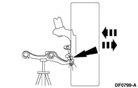
4. While an assistant pulls and pushes the bottom of the tire, observe the relative movement between the lower spindle arm and the front suspension lower arm ball joint. Any movement at or exceeding the specification indicates a worn or damaged lower ball joint. Install a new front suspension lower arm.
Wheel Bearing Inspection
1. Raise the vehicle until the tire is off the floor.
2. NOTE: Make sure the wheel rotates freely and the brake pads are retracted sufficiently to allow movement of the tire and wheel assembly.
Grasp each tire at the top and bottom and move the wheel inward and outward while lifting the weight of the tire off the wheel bearing.
3. If the tire and wheel (hub) is loose on the wheel spindle or does not rotate freely, install a new front wheel hub (1104) as necessary.
 Symptom Chart
Condition
Possible Sources
Action
Dogtracking
Excessive rear
thrust angle.
Front or rear
suspension
components.
Drive axle
damaged.
...
 Camber and Caster Adjustment - Front
All vehicles
1. Remove the rivet. Loosen the nuts and bolt.
Vehicles requiring camber adjustment
2. Move the front suspension camber adjusting plate (3B391) to the required
camber setting.
Vehicl ...
Other materials:
Cruise Control
PRINCIPLES OF OPERATION
Cruise control lets you maintain a set speed without keeping your foot
on the accelerator pedal.
USING CRUISE CONTROL
WARNING: Do not use cruise control in heavy traffic, on
winding roads or when the road surface is slippery. This coul ...
Idle Air Control (IAC) Valve - 3.8L
Removal
1. Disconnect the battery ground cable. For additional information,
refer to Section.
2. NOTE: Discard the idle air control (IAC) valve gasket.
Remove the IAC valve.
Disconnect the connector.
Remove the two bolts, the IAC valve and ...
Removal
1. Disconnect the battery negative cable.
2. Drain the engine cooling system.
3. Remove the RH exhaust manifold. For additional information, refer to Exhaust
Manifold RH in
this section.
4. Remove the lower intake manifold. For additional information, re ...
