Ford Mustang (1999-2004) Service Manual: Disassembly
1. Remove the differential assembly from the differential housing. For additional information, refer to Differential Case in this section.
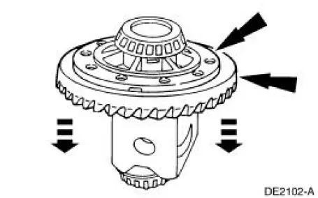
2. Remove the bolts.
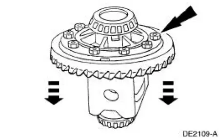
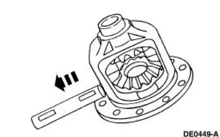
3. CAUTION: Do not damage the threads in the bolt holes.
Insert a punch in the bolt holes and drive off the ring gear.
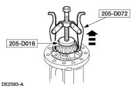
4. Using the special tools, remove the differential bearings (4221), if necessary.
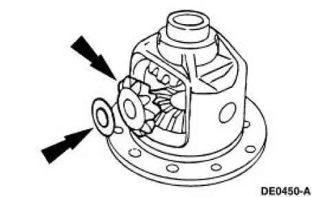
5. Remove the bolt.
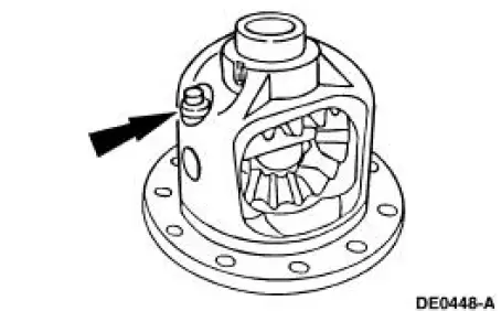
6. Remove the differential pinion shaft (4211).
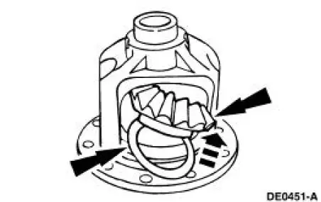
7. Rotate and remove the differential pinion gears (4215) and differential pinion thrust washers (4230).
8. Remove the differential side gears (4236) and the differential side gear thrust washers (4228).
 Differential Case and Ring Gear
Special Tool(s)
2-Jaw Puller
205-D072 (D97L-4221-A) or
equivalent
Installer, Differential Side
Bearing
205-009 (T57L-4221-A1)
Step Plate
205-D016 (D80L-630-5) or
...
 Assembly
1. Lubricate the differential side gear thrust washers and the differential
side gear journals, and
assemble the washers to the gears.
Use SAE 80W-90 Premium Rear Axle Lubricant XY-80W90-QL or equi ...
Other materials:
Brake Booster - Hydro-Boost (Description and Operation)
The Hydro-Boost brake booster is a hydraulically operated brake booster
powered by the power
steering pump (3A674). The power steering pump provides the fluid pressure to
operate both the
power brake booster and the power steering gear (3504).
A Hydro-Boost ...
Condenser Core
Material
Item
Specification
PAG Refrigerant Compressor
Oil (R-134a Systems)
F7AZ-19589-DA (Motorcraft YN-
12-C)
WSH-M1C231-
B
Removal and Installation
NOTE: If an A/C condenser core leak is suspected, the A/C condenser
core must be l ...
Steering Column (Description and Operation)
NOTE: All fasteners are important because they can affect the
performance of vital parts and systems.
Incorrect installation of the fasteners can result in major repair expenses.
They must be installed new
with fasteners of the same part number ...
