Ford Mustang (1999-2004) Service Manual: Disassembly
1. Remove the driveshaft (4602). For additional information, refer to Driveshaft in this section.
2. CAUTION: Under no circumstances is the driveshaft assembly to be clamped in the jaws of a vise or similar holding fixture. Denting or localizing fracture can result, causing driveshaft failure during vehicle operation.
Place the driveshaft (4602) on a suitable workbench. Be careful not to damage the tube.
3. NOTE: If components are not marked and therefore installed incorrectly, driveline imbalance can occur.
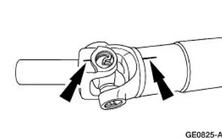
Index-mark the driveshaft components.
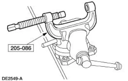
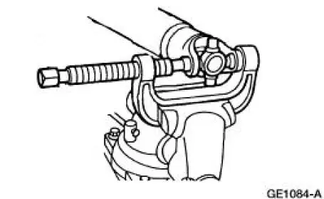
4. Clamp the special tool in a vise.
5. Remove all four of the snap rings.
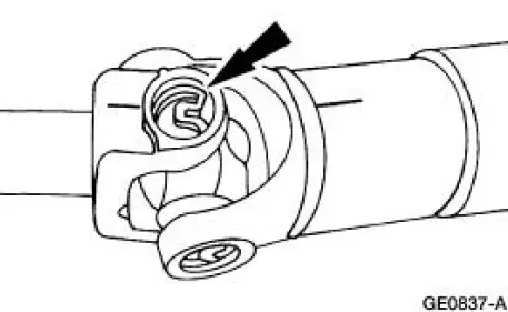
6. NOTE: If necessary, use a pair of pliers to remove a bearing cup if it cannot be pressed out all the way.
Remove the driveshaft slip yoke (4841).
1. Position the driveshaft slip yoke in the U-joint tool.
2. Press out a bearing cup.
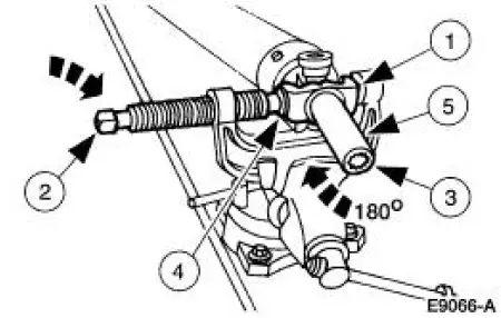
3. Rotate the driveshaft slip yoke.
4. Press on the spider to remove the remaining bearing cup.
5. Remove the driveshaft slip yoke.
7. Repeat Step 5 to remove the remaining bearing cups and spider from the driveshaft.
8. Clean the yoke area at each end of the driveshaft.
 Driveshaft Slip Yoke
Special Tool(s)
Installer/Remover, C Frame
and Screw
205-086 (T74P-4635-C)
...
 Assembly
1. NOTE: Universal joint service kits are to be installed as complete
assemblies only. Do not mix
components from other U-joint kits.
Install the bearing cup.
1. Start a new bearing cup into the d ...
Other materials:
Pilot Bearing
Special Tool(s)
Puller with Slide Hammer
308-001 (T58L-101-B)
1. Remove the clutch disc and the clutch pressure plate. For additional
information, refer to Disc
and Pressure Plate-3.8L and 4.6L (2V) Engines or Disc and Pressure Plate-4.6L
(4V ...
Mass Air Flow (MAF) Sensor - Mach I
Removal
CAUTION: The mass air flow (MAF) sensor hot wire sensing
element and housing are
calibrated as a unit and must be repaired as a complete assembly. Do not
damage the sensing
element (internal to housing) or possible failure to the mass air f ...
Cleaning the windows and wiper blades
The windows and wiper blades should be cleaned regularly. If the wipers
do not wipe properly, substances on the vehicle’s glass or the wiper
blades may be the cause. These may include hot wax treatments used by
commercial car washes, water repellent coatings ...
