Ford Mustang (1999-2004) Service Manual: Removal
1. Raise and support the vehicle.
2. Remove the rear wheel and tire assemblies.
3. CAUTION: Remove the rear brake calipers to prevent drag during the drive pinion bearing preload adjustment.
CAUTION: Do not allow the calipers to hang from the brake hoses.
Remove the rear brake caliper and support bracket from the knuckle as an assembly. Wire the caliper and support bracket assembly out of the way.
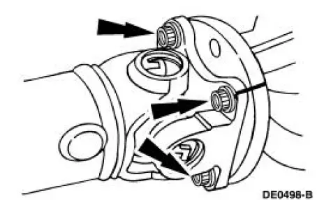
4. CAUTION: Index-mark the driveshaft flange and pinion flange (4851) to maintain initial balance during installation.
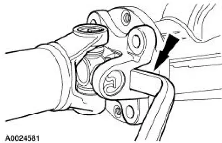
CAUTION: The driveshaft centering socket yoke fits tightly on the pinion flange pilot. Never hammer on the driveshaft or any of its components to disconnect the yoke from the flange. Pry only in the area shown, with a suitable tool, to disconnect the yoke from the flange.
Disconnect and position the driveshaft out of the way.
5. Install an Nm (inch/pound) torque wrench on the nut and record the torque necessary to maintain rotation of the drive pinion gear through several revolutions.
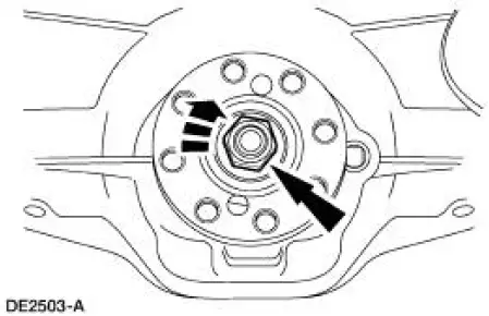
6. CAUTION: After removing the nut, discard it. Use a new nut for installation.
Use the special tool to hold the pinion flange while removing the nut.
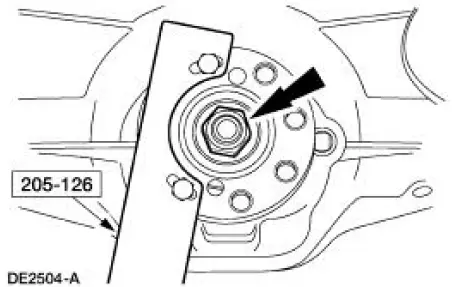
7. Index-mark the pinion flange and drive pinion gear stem to maintain initial balance during installation.
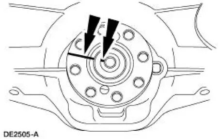
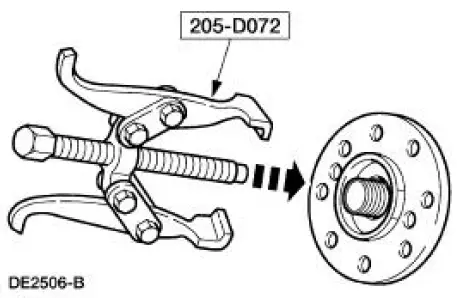
8. Using the special tool, remove the pinion flange.
 Drive Pinion Flange and Drive Pinion Seal
Special Tool(s)
2-Jaw Puller
205-D072 (D97L-4221-A) or
equivalent
Holding Fixture, Drive Pinion
Flange
205-126 (T78P-4851-A)
Installer, Drive Pinion Flange
205-002 ...
 Installation
1. Inspect the pinion flange seal journal for rust, nicks, and scratches
prior to installing the flange.
Polish the seal journal with fine crocus cloth, if necessary.
2. Lubricate the pinion flange ...
Other materials:
Front passenger sensing system
WARNING: Even with Advanced Restraints Systems, children 12
and under should be properly restrained in a rear seating
position. Failure to follow this could seriously increase the risk of injury
or death.
WARNING: Sitting improperly out of position or with the ...
Instrument Cluster (Description and Operation)
The instrument cluster (10849) consists of the following components:
Instrument Cluster-Base 3.8L Engine
Instrument Cluster-Base 4.6L Engine
Instrument Cluster-Cobra
...
Plenum Chamber
Removal
1. Remove the instrument panel. For additional information, refer to Section.
2. Remove the audio unit. For additional information, refer to Section.
3. If equipped, remove the CD player. For additional information, refer to
Section.
4. Remove the ...
