Ford Mustang (1999-2004) Service Manual: Final assembly
23. Install the differential assembly in the differential housing. For additional information, refer to Differential Case in this section.
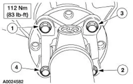
24. CAUTION: Align the index marks.
CAUTION: Install the driveshaft with new bolts. If new bolts are not available, apply Threadlock and Sealer EOAZ-19554-AA or equivalent meeting Ford specification WSKM2G351- A5 to the threads of the original bolts.
CAUTION: The driveshaft centering socket yoke fits tightly on the pinion flange pilot. To make sure that the yoke seats squarely on the flange, tighten the bolts evenly in a cross pattern as shown.
Connect the driveshaft.
25. Lower the vehicle.
 Installation
Using special tool 205-024
NOTE: This is the preferred method for installing the pinion bearing
cups. If necessary, proceed to
Using special tools 205-153, 205-024, 205-231, and 205-D055 in this proc ...
 Differential Case
Special Tool(s)
2-Jaw Puller
205-D072 (D97L-4221-A) or
equivalent
Dial Indicator Gauge with
Holding Fixture
100-002 (TOOL-4201-C) or
equivalent
Gauge, Clutch Hou ...
Other materials:
Air Cleaner Element - 4.6L (2V)
Removal and Installation
1. Remove the air cleaner outlet tube (9B659). For additional
information, refer to Air Cleaner
Outlet Pipe-4.6L (2V) in this section.
2. Remove the mass air flow (MAF) assembly.
1. Release the clip.
2. Remove the MAF sens ...
Axle Assembly
Removal and Installation
1. CAUTION: The vehicle must be on level ground and at curb height.
Mark the rear shock absorbers relative to their protective sleeve.
During installation, raise the suspension to this reference mark before
tightening the
suspens ...
Battery and Cables
Vehicles are equipped with a 12 volt maintenance-free battery that
contains a built-in hydrometer. The
hydrometer eye indication is as follows:
A green dot means the battery is OK.
A yellow dot, red dot, or when the green dot is not visible,
...
