
Ford Mustang (1999-2004) Service Manual: Torque Converter (Description and Operation)
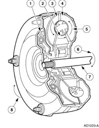
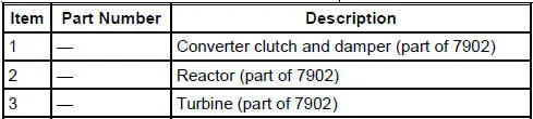
The torque converter transmits and multiplies torque. The torque converter is a four-element device:
- impeller assembly
- turbine assembly
- reactor assembly
- clutch and damper assembly
The standard torque converter components operate as follows:
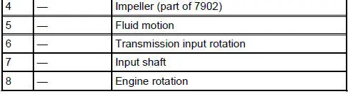
- Rotation of the converter housing and impeller set the fluid in motion.
- The turbine reacts to the fluid motion from the impeller, transferring rotation to the geartrain through the input shaft.
- The reactor redirects fluid going back into the impeller, allowing for torque multiplication.
- The clutch and damper assembly dampens powertrain torsional vibration and provides a direct mechanical connection for improved efficiency.
- Power is transmitted from the torque converter to the planetary gearsets and other components through the input shaft.
 Shift Patterns
Upshifts
Transmission upshifting is controlled by the powertrain control
module (PCM). The PCM receives
inputs from various engine or vehicle sensors and driver demands to
control shift sche ...
 Geartrain
Power is transmitted from the torque converter to the Ravigneaux
geartrain components through the
input shaft and forward clutch cylinder.
The geartrain contains a Ravigneaux planetary set ...
Other materials:
Sprockets
1. WARNING: To avoid the possibility of personal injury or damage
to the vehicle, do
not operate the engine with the hood open until the fan blade has been
examined for
possible cracks and separation.
NOTE: Specifications show the expected minimum or ma ...
Appendices
GENERAL INFORMATION
SYNC® End User License Agreement (EULA)
• You have acquired a device (“DEVICE�) that includes software
licensed by FORD MOTOR COMPANY from an affiliate of Microsoft
Corporation (“MS�). Those installed software products of MS orig ...
Windshield wipers
Note: Fully defrost the windshield before switching on the windshield
wipers.
Note: Make sure you switch off the windshield wipers before entering a
car wash.
Note: Clean the windshield and wiper blades if they begin to leave
streaks or smears. If that does ...
