Ford Mustang (1999-2004) Service Manual: Installation
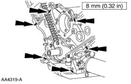
1. Apply silicone gasket and sealant in the locations shown.
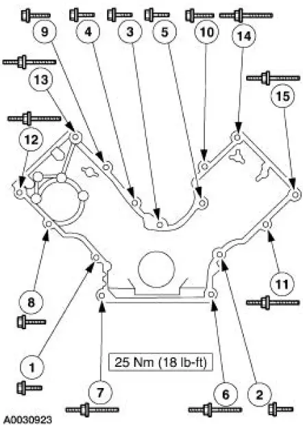
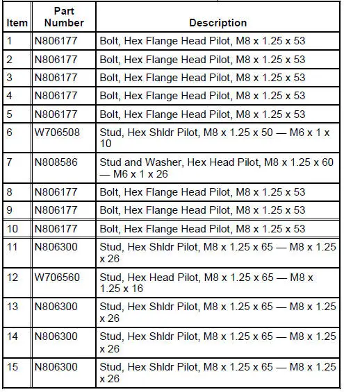
2. Install the engine front cover.
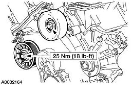
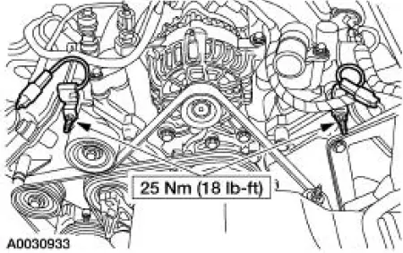
3. Install the belt idler pulleys and the bolts.
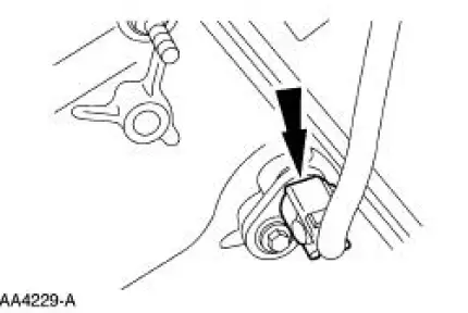
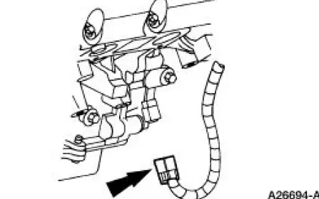
4. Connect the CMP sensor electrical connector.
5. Raise the vehicle.
6. Install the crankshaft front oil seal. For additional information, refer to Crankshaft Front Oil Seal in this section.
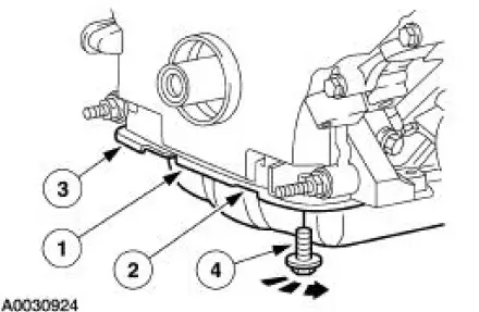
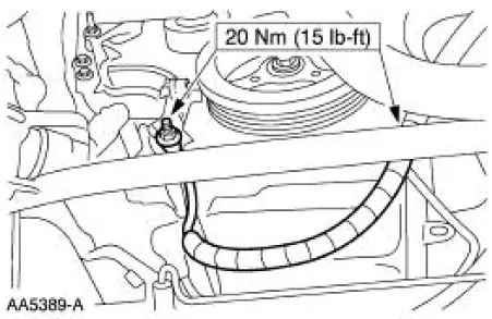
7. Tighten the four oil pan bolts in the sequence shown.
- Stage 1: Tighten to 2 Nm (18 lb-in).
- Stage 2: Tighten to 20 Nm (15 lb-ft).
- Stage 3: Tighten an additional 60 degrees.
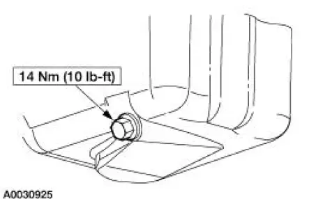
8. Install the drain plug.
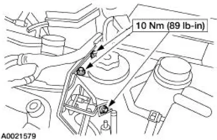
9. Position the power steering reservoir and install the bolts.
10. Connect the CKP sensor electrical connector.
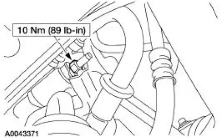
11. Position the A/C muffler and tighten the nut.
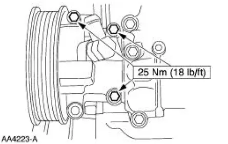
12. Install the power steering pump and the bolts.
13. Position the battery cable and install the two nuts.
14. Install the crankshaft pulley. For additional information, refer to Crankshaft Pulley in this section.
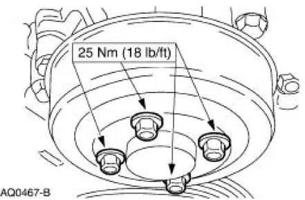
15. Install the water pump pulley and the bolts.
16. Install the cooling fan.
17. Install the accessory drive belt. For additional information, refer to Section
18. Install the valve covers. For additional information, refer to Valve Cover RH and Valve Cover LH in this section.
19. Position the radio ignition interference capacitors and install the nuts.
20. Fill the crankcase with clean engine oil.
 Removal
1. Remove the nuts and position the radio ignition interference capacitors
aside.
2. Remove the valve covers. For additional information, refer to Valve Cover
RH and Valve Cover
LH in this section ...
 Timing Drive Components
Special Tool(s)
Compressor, Valve Spring
303-567 (T97P-6565-AH)
Holding Tool, Crankshaft
303-448 (T93P-6303-A)
Aligner, Camshaft Position
303-557 (T96T-6256-B) ...
Other materials:
Brake Caliper Anchor Plate
Removal
1. Remove the pads. For additional information, refer to Pads in this
section.
2. Remove the anchor plate (2B292).
1. Remove and discard the anchor plate bolts.
2. Remove the anchor plate.
Installation
1. CAUTION: Use correct t ...
Manual Transaxle/Transmission - T56
General Specifications
Torque Specifications
...
Pinpoint Test E: LFC 15/DTC B1916 - Driver Air Bag Circuit Shorted to
Battery or Ignition
Normal Operation
The restraints control module (RCM) checks for driver air bag circuit
shorts to battery or ignition by
monitoring the voltage of circuit 614 (GY/OG) and 615 (GY/WH) at pins 3 and
4. If the RCM detects a
short to battery or ignition on e ...
