Ford Mustang (1999-2004) Service Manual: Installation
1. NOTE: If the valve cover is not secured within four minutes, the sealant must be removed and the sealing area cleaned with metal surface cleaner. Allow to dry until there is no sign of wetness, or four minutes, whichever is longer. Failure to follow this procedure can cause future oil leakage.
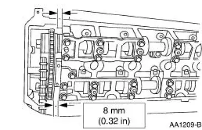
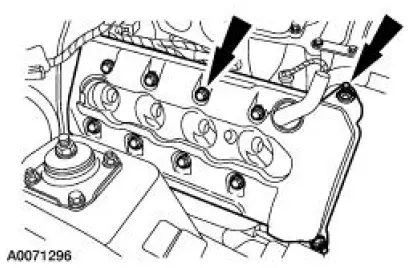
Apply a bead of silicone gasket and sealant in two places where the engine front cover meets the cylinder head.
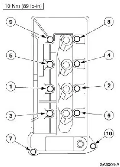
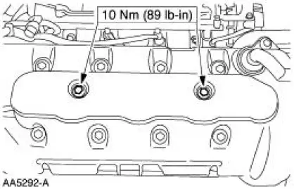
2. Install the RH valve cover and finger tighten the bolts.
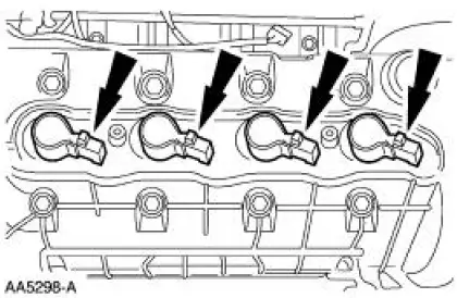
3. Tighten the RH valve cover bolts in the sequence shown.
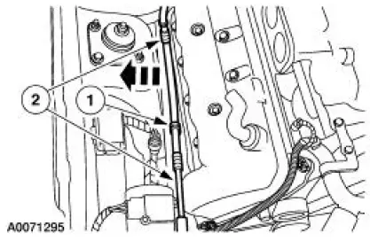
4. Connect the wiring harness to the valve cover stud bolt.
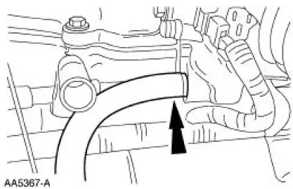
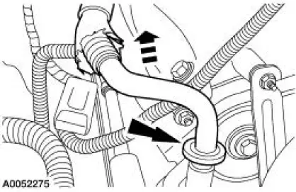
5. Connect the evaporative emissions (EVAP) return tube.
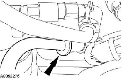
6. NOTE: Lubricate O-ring with clean PAG oil or equivalent.
Install the A/C tube.
1. Install the A/C tube.
2. Connect the pin-type retainer.
7. NOTE: Lubricate O-ring with clean PAG oil or equivalent.
Connect the A/C tube to the evaporator.
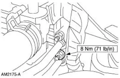
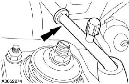
8. Connect the A/C tube and install the nut.
9. NOTE: Lubricate O-ring with clean PAG oil or equivalent.
Install the A/C suction tube.
10. NOTE: Lubricate O-ring with clean PAG oil or equivalent.
Connect the A/C suction tube to the accumulator.
11. Connect the heater hose.
12. Install the throttle body. For additional information, refer to Section.
13. Connect the fuel tube spring lock coupling. For additional information, refer to Section.
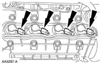
14. Install the RH ignition coils.
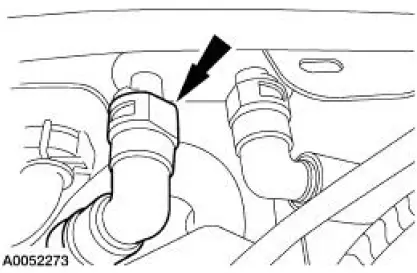
15. Connect the RH ignition coil electrical connectors.
16. Install the RH ignition coil cover and the two bolts.
17. Install the air cleaner outlet tube. For additional information, refer to Section.
18. Connect the battery ground cable. For additional information, refer to Section.
19. Fill the cooling system. For additional information, refer to Section .
20. Recharge the A/C system. For additional information, refer to Section.
 Removal
1. Disconnect the battery ground cable. For additional information, refer to
Section.
2. Drain the cooling system. For additional information, refer to Section.
3. Recover the refrigerant. For addi ...
 Valve Cover LH
Material
Item
Specification
Metal Surface Cleaner
F4AZ-19A536-RA or
equivalent
WSE-M5B392-A
Silicone Gasket and Sealant
F7AZ-19554-EA or equivalent
WSE-M4G323-
A4
...
Other materials:
Brake Pads - Cobra
Removal
1. Remove brake fluid in the master cylinder reservoir until the
reservoir is half full.
2. Raise and support the vehicle.
3. Remove the tire and wheel assembly.
4. CAUTION: Install new pads if worn to or past the specified
thi ...
Removal
1. Disconnect the battery negative cable.
2. Drain the engine cooling system.
3. Remove the RH exhaust manifold. For additional information, refer to Exhaust
Manifold RH in
this section.
4. Remove the lower intake manifold. For additional information, re ...
Seats (Description and Operation)
Seats - Front Power
The front power seat features:
a six-way seat regulator control switch (14A701) located on the
front of the seat.
a seat track (61705) mounted under the seat.
a seat regulator motor (14547) and gear housing mounted on ...
