Ford Mustang (1999-2004) Service Manual: Lead Terminal Repair
Special Tool(s)
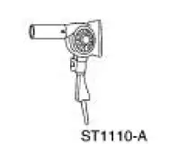 |
Heat Gun 107-R0300 or equivalent |
Material
| Item | Specification |
| Rear Window Defroster Repair D8AZ-19562-AA | WSB-M4J58-B |
1. NOTE: The rear window glass must be at room temperature at the time of the repair.
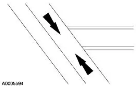
Clean the bus bar in the area to be repaired with steel wool (3/0 to 4/0 grade).
2. NOTE: Allow 10 minutes of drying time between the coats.
Apply three coats of rear window defroster repair to the surface.
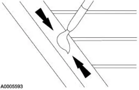
3. CAUTION: Do not overheat the rear window glass or damage to the rear window glass may occur.
Tin the bus bar repair area with solder.
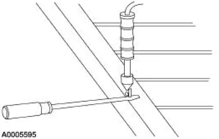
4. CAUTION: To prevent overheating the rear window glass, remove the soldering gun as soon as the solder flows.
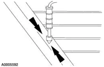
Preheat the rear window glass in the area to be repaired using the special tool and solder the terminal to the bus bar.
5. NOTE: Turn the heated rear window switch ON for five minutes prior to the final inspection of the repair.
Apply rear window defroster repair to the area as needed.
 Heated Window Grid Wire Repair
Material
Item
Specification
Dark Walnut Metallic Acrylic
Lacquer Touch-up Paint
ALBZ-19500-5858A or
equivalent
ESR-M2-P100-
C
Rear Window Defroster Repair
D8AZ-19562-AA ...
 Door Window Glass Adjustment - Height Stop Adjustment
1. Close the front door.
2. Loosen the screws.
3. Raise the door window glass to the desired height.
4. Tighten the screws.
Door Window Glass Adjustment -Stabilizer
1. Raise the door window ...
Other materials:
Engine oil check
Note: Check the level before starting the engine.
Note: Make sure that the level is between the MIN and MAX marks.
1. Make sure that your vehicle is on level ground.
2. Turn the engine off and wait 10 minutes for the oil to drain into the
oil pan.
3. Remove ...
Installation
1. CAUTION: Install the brake pads in full axle sets. Do not
install new brake pads on
only one side of vehicle.
Install the new slipper and brake pads.
2. Position the caliper on the anchor plate and install the bolts.
3. Install the wheel and tire ...
Transmission (Assembly)
Special Tool(s)
Dial Indicator Gauge with
Holding Fixture
100-002 (TOOL-4201-C) or
equivalent
Holding Fixture, Transmission
307-003 (T57L-500-B)
Remover/Installer, Bearing
Tube
308-024 (T75L-7025-B)
Re ...
