
Ford Mustang (1999-2004) Service Manual: Synchronizers
Disassembly and Assembly
NOTE: This procedure applies to all synchronizer assemblies.
1. NOTE: Synchronizer components are not interchangeable. During disassembly, mark each individual synchronizer for assembly. Synchronizer hubs and sleeves are a selected assembly and should be kept together as originally assembled. Blocking rings are not interchangeable, do not mix.
Scribe an alignment mark on the sliding sleeve and the hub for assembly reference.
2. Using a screwdriver, remove the spring. Turn the synchronizer over and remove the second spring. Remove the sliding sleeve and the synchronizer struts from the hub.
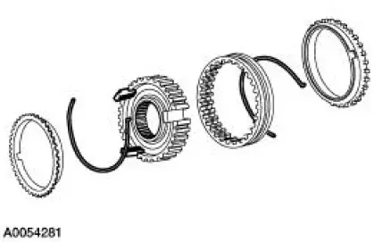
3. CAUTION: Match the alignment marks made during disassembly. The sleeve and the hub have an extremely close fit. Hold the sleeve and hub square to prevent jamming.
Do not force the sleeve onto the hub.
Assemble the synchronizer as follows:
- Position the synchronizer sleeve on the hub. Make sure to align key openings in the hub with the synchronizer sleeve.
- Install the keys with the slots facing the hub.
- Install the spring. Locate the tang to one of the key slots and position into place. Install the second spring. Locate the spring tang on the same key but position in the opposite direction.
 Countershaft
Special Tool(s)
Plate, Bearing Oil Seal
205-090 (T75L-1165-B)
Puller, Bearing
205-D064 (D84L-1123-A)
Installer, Drive Pinion Bearing
Cone
205-004 (T53T-4621- ...
 Gearshift Rail and Fork
Disassembly and Assembly
1. Disassemble the first/second and third/fourth shift rail as follows:
Rotate the interlock plate until it is opposite of the shift links.
Slide off the third/fo ...
Other materials:
Air Conditioning (A/C) System Recovery, Evacuation and Charging
Special Tool(s)
R-134a A/C Refrigerant Center
176-00002 or equivalent
R-134a A/C Refrigerant Center
023-00153 or equivalent
R-134a Manifold Gauge Set
176-R032A or equivalent
1.2 CFM Vacuum Pump
023-00162 o ...
Steering Column Shaft
Removal and Installation
1. CAUTION: Do not allow the steering column shaft to rotate while
intermediate shaft
is disconnected or damage to the clockspring can result. If there is evidence
that the
steering column shaft has rotated the clockspring must be re ...
Inspection and Verification
1. Verify the customer concern by operating the engine to duplicate the
condition.
2. Visually inspect for obvious signs of mechanical damage. Refer to the
following chart.
Visual Inspection Chart
Mechanical
Engine coolant leaks
...
