Ford Mustang (1999-2004) Service Manual: Transmission (Removal)
1. Remove the gearshift lever knob.
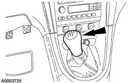
2. Remove the console panel gearshift plate. Disconnect the cigar lighter electrical connector, then lift the gearshift lever boot over the gearshift lever.
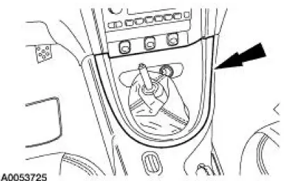
3. Remove the bolts and the upper gearshift lever.
4. Remove the bolts and the lower gearshift lever boot.
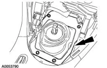
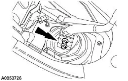
5. Remove the bolts and the lower gearshift lever.
6. Disconnect the reverse lockout solenoid electrical connector.
7. With the vehicle in NEUTRAL, raise and support the vehicle.
8. Drain the transmission fluid.
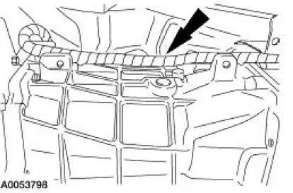
9. CAUTION: Index-mark the driveshaft flange and pinion flange, and the driveshaft slip yoke and transmission output shaft.
Remove the driveshaft. For additional information, refer to Section.
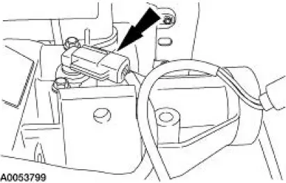
10. Disconnect the heated oxygen sensor (HO2S) electrical connectors from the crossmember.
11. Position a transmission jack and support the transmission.
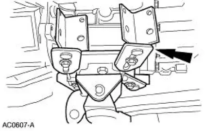
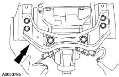
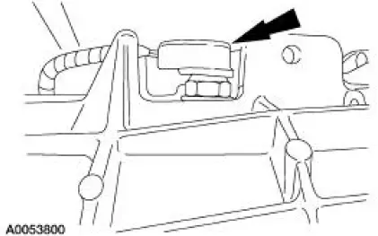
12. Remove the bolts and the transmission crossmember.
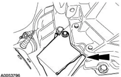
13. Remove the bolt and the clutch release lever cover.
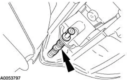
14. Disengage the clutch release cable from the clutch release fork.
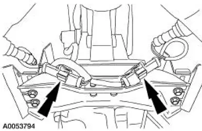
15. Disconnect the wiring harness from the transmission.
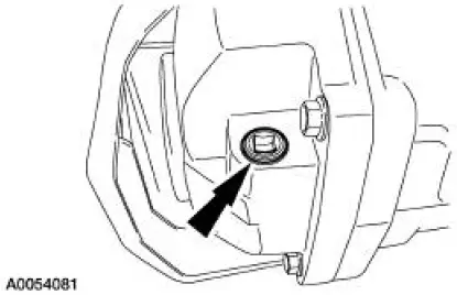
16. Disconnect the output shaft speed (OSS) sensor electrical connector.
17. Disconnect the reverse lamp electrical connector.
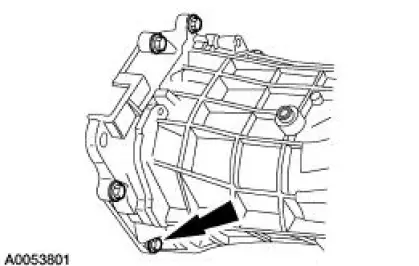
18. Remove the eight transmission-to-clutch adapter housing bolts.
19. Move the transmission rearward until the input shaft is clear of the pressure plate, then lower the rear of the transmission while moving it forward to clear the exhaust pipe. Lower the transmission from the vehicle.
 Transmission Draining and Filling
Material
Item
Specification
DEXRON III (ATF)
Transmission Fluid
XT-2-QDX
DEXRON III
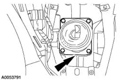
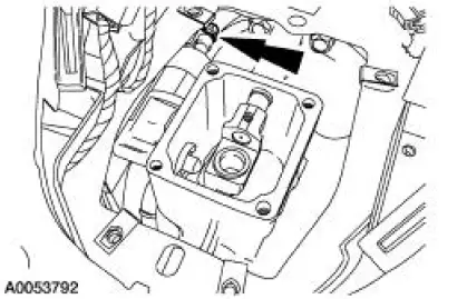
1. Remove the drain plug and drain the transmission.
Position a suitable drain pan under the ...
 Transmission (Disassembly)
Special Tool(s)
Holding Fixture, Transmission
307-003 (T57L-500-B)
Puller, Bearing
205-D064 (D84L-1123-A)
2 or 3 Jaw Puller
205-D027 (D80L-1013-A)
...
Other materials:
Parking brake
WARNING: If the parking brake is fully released, but the brake
warning lamp remains illuminated, the brakes may not be
working properly. See your authorized dealer as soon as possible.
WARNING: Always set the parking brake fully and make sure
that the transmis ...
Emission control system
WARNING: Do not park, idle, or drive your vehicle in dry grass
or other dry ground cover. The emission system heats up the
engine compartment and exhaust system, which can start a fire.
WARNING: Exhaust leaks may result in entry of harmful and
potentially leth ...
Installation
CAUTION: The upper suspension arm and bushing nuts must be tightened
with the
suspension at curb height. Failure to do so can result in bushing failure,
resulting in poor ride
and handling.
NOTE: If installing a new upper suspension arm and bushing, mark the ...
