Ford Mustang (1999-2004) Service Manual: Valve - Seat Inspection
Valve and Seat Refacing Measurements
CAUTION: After grinding valves or valve seats, check valve clearance.
1. Check the valve head and seat.
- Check valve angles.
- Check margin width.
- Refer to the appropriate section in Group 303 for the procedure.
- Be sure margin width is within specification.
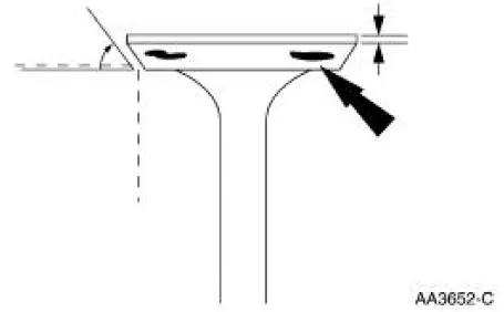
2. Inspect for abnormalities on the valve face and seat.
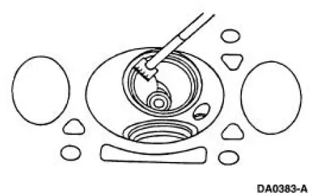
Valve -Seat Width
1. Measure the valve seat width. If necessary, grind the valve seat to specification.
- Measure the intake valve seat width.
- Measure the exhaust valve seat width.
- Recheck the valve spring installed length after the seats have been ground, and shim the valve springs as necessary to achieve the correct installed spring length.
- Refer to the appropriate section in Group 303 for the procedure.
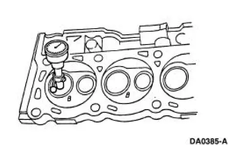
Valve -Seat Runout
1. Use the Valve Seat Runout Gauge to check valve seat runout.
 Valve Spring Strength
Special Tool(s)
Pressure Gauge, Valve/Clutch
Spring
303-006 (TOOL-6513-DD) or
equivalent
1. Use a Valve/Clutch Spring Pressure Gauge to check the valve spring for
correct strength ...
 Cylinder Head - Distortion
Special Tool(s)
Straight Edge
303-D039 (D83L-4201-A) or
equivalent
1. Use a straight edge and a feeler gauge to inspect the cylinder head for
flatness. If the cylinder
head is disto ...
Other materials:
Bulb
Removal and Installation
1. Remove the floor console. For additional information, refer to
Section.
2. Remove the bolts, then position the bezel upward.
3. Remove the bulb socket from the bezel.
4. Remove the bulb.
5. To install, reverse the removal ...
Switch - Key-In-Ignition Warning
Removal
1. Remove the ignition switch lock cylinder.
1. Insert the ignition key and turn to the RUN position.
2. Insert a punch in the access hole of the steering column and
press the release tab while
pulling out the ignition switch lock cy ...
Driveline System - General Information
Driveline Angles @ Curb Specifications
All driveshaft and pinion angles point downward.
General Specifications
a: Service refill capacities are determined by filling the axle 6.3 mm (0.25
in [1/4 in]) to 14.3 mm (0.57 in
[5/16 in]) below the bottom of the ...
