Ford Mustang (1999-2004) Service Manual: Installation
1. Install the bearing, snap ring, hub and dust shield. For additional information, refer to Wheel Hub-Cobra in this section.
2. Install the knuckle.
1. Position the knuckle on the lower suspension arm and bushing.
2. Install a new bolt and a new nut. Do not tighten the nut at this time.
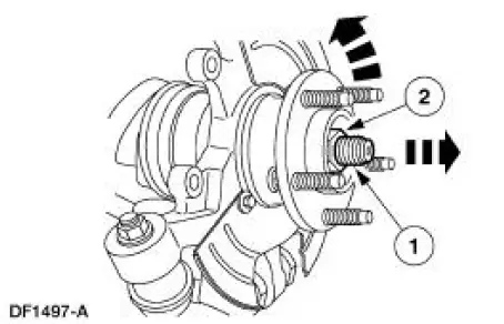
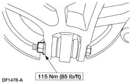
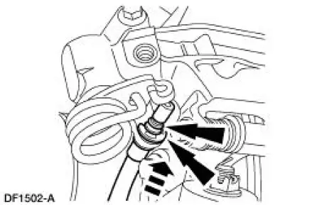
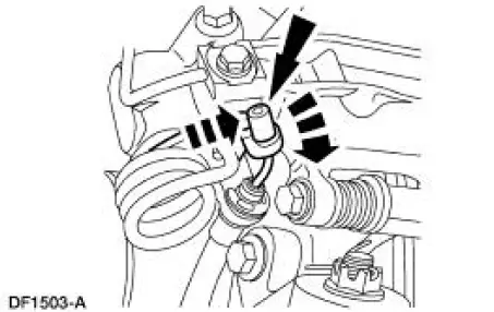
3. Connect the axle shaft to the hub.
1. Making sure the splines on the shaft line up with the splines in the hub, install the axle shaft into the hub.
2. Install a new retainer. Do not tighten the retainer at this time.
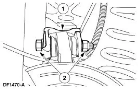
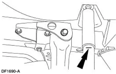
4. Connect the upper suspension arm and bushing to the knuckle.
1. Position the upper suspension arm and bushing on the knuckle.
2. Install a new cam bolt and a new nut. Do not tighten the nut at this time.
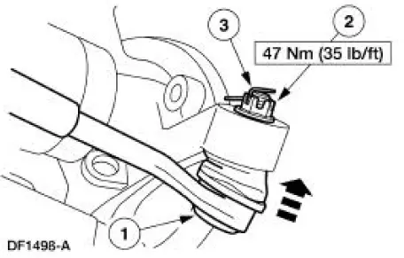
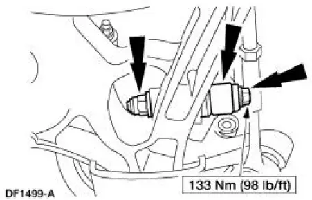
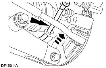
5. Connect the toe link to the knuckle.
1. Position the toe link in the knuckle.
2. Install a new nut.
3. Install a new cotter pin
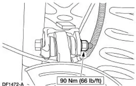
6. CAUTION: Make sure the hardened washer is installed between the lower suspension arm and bushing and the shock absorber. Failure to do so can result in damage and failure of the lower suspension arm and bushing.
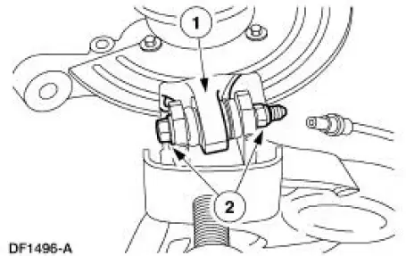
Connect the shock absorber to the lower suspension arm and bushing and install the bolt and a new nut.
7. Raise the suspension until the shock absorber is compressed to the previously established alignment mark (curb height).
8. Tighten the nut.
9. Make sure the marks on the cam bolt and the upper suspension arm and bushing made during removal are aligned, and tighten the nut.
10. Lower the suspension and remove the jack stand.
11. Install the rear brake disc.
12. Install the parking brake cable and conduit into the knuckle.
13. Connect the parking brake cable and conduit to the rear brake caliper and install the clip.
14. Connect the parking brake cable and conduit to the parking brake lever.
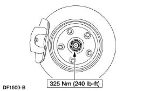
15. CAUTION: The axle retainer must be tightened with the brakes applied and the wheels off the ground to make sure of correct bearing seating. Failure to do so can cause the retainer to loosen, causing extensive vehicle damage and loss of vehicle control.
Lower the vehicle and apply the parking brake or service brakes.
16. Tighten the retainer.
17. Install the wheel and tire assembly.
18. Lower the vehicle.
19. Check the wheel alignment. Adjust as necessary.
 Removal
CAUTION: Suspension fasteners are critical parts because they affect
performance of vital
components and systems and their failure can result in major service expense. A
new part with
the same part ...
 Toe Link - Cobra
Special Tool(s)
Steering Arm Remover
211-003 (T64P-9171-A)
...
Other materials:
Fuel Vapor Control Tube Assembly Valve
Removal and Installation
1. Remove the fuel tank. For additional information, refer to
Section.
2. Remove the retainers.
3. NOTE: The fuel vapor vent valve, fuel vapor control valve and the
in-line fuel tank pressure
sensor are repaired as a fuel va ...
Rear Drive Axle/Differential - Ford 8.8-Inch Ring Gear
General Specifications
Torque Specifications
Description
Nm
lb-ft
lb-in
Bolt retaining the differential pinion shaft to the
differential case
30
22
-
Bolt retaining the driveshaft yoke to the pinion flange
112
83
-
...
Installation
1. CAUTION: Install the brake pads in full axle sets. Do not
install new brake pads on
only one side of vehicle.
Install the new slipper and brake pads.
2. Position the caliper on the anchor plate and install the bolts.
3. Install the wheel and tire ...
