Ford Mustang (1999-2004) Service Manual: Removal
CAUTION: Suspension fasteners are critical parts because they affect performance of vital components and systems and their failure can result in major service expense. A new part with the same part number must be installed if installation becomes necessary. If substitution is necessary, the part must be of the same finish and property class. Torque values must be used as specified during reassembly to make sure of correct retention of these parts.
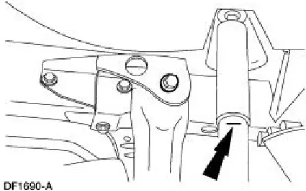
1. Mark the rear shock absorber (18125) relative to the protective sleeve with the vehicle in a static, level ground position (curb height).
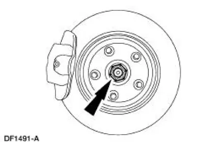
2. Raise the vehicle on a hoist. 3. Remove the wheel and tire assembly. 4. Remove and discard the rear hub retainer (4B477).
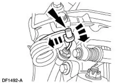
5. Disconnect the parking brake cable and conduit from the parking brake lever.
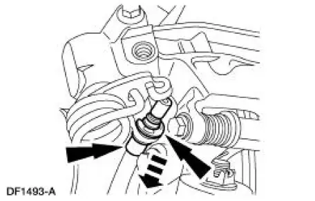
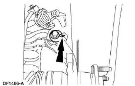
6. Remove the clip and disconnect the parking brake cable and conduit from the rear brake caliper.
7. Disconnect the parking brake cable and conduit from the knuckle (5A968/5A969).
8. Remove the rear brake disc.
9. Support the lower suspension arm and bushing (5A649) with a jack stand.
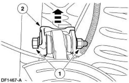
10. Remove the nut and bolt and disconnect the shock absorber (18125) from the lower suspension arm and bushing. Discard the nut and bolt.
11. Remove and discard the cotter pin and nut.
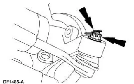
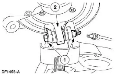
12. CAUTION: Do not strike the toe link or the knuckle to disconnect the toe link. The toe link or the knuckle can be damaged.
Using the special tool, disconnect the toe link (5K899) from the knuckle.
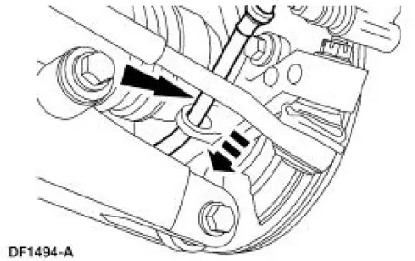
13. Mark the cam bolt position relative to the upper suspension arm and bushing (5500).
14. NOTE: Mark a new cam bolt in the same position as the old one for assembly reference before discarding the old bolt.
Disconnect the upper suspension arm and bushing from the knuckle.
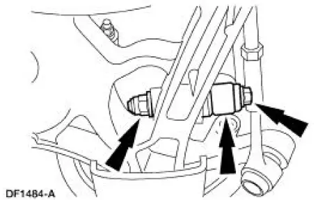
1. Remove and discard the nut and bolt.
2. Disconnect the arm and bushing from the knuckle.
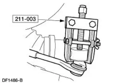
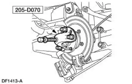
15. Using the special tool, press the axle shaft from the hub (1109).
16. Remove the knuckle from the lower arm and bushing.
1. Remove and discard the nut and bolt.
2. Remove the knuckle.
17. Remove the dust shield, hub, snap ring and bearing from the knuckle. For additional information, refer to Wheel Hub-Cobra in this section.
 Wheel Knuckle - Cobra
Special Tool(s)
Front Hub Remover
205-D070 (D93P-1175-B) or
Equivalent
Steering Arm Remover
211-003 (T64P-9171-A)
...
 Installation
1. Install the bearing, snap ring, hub and dust shield. For additional
information, refer to Wheel
Hub-Cobra in this section.
2. Install the knuckle.
1. Position the knuckle on the lower suspensio ...
Other materials:
Camshaft
Material
Removal
1. Remove the valve tappets. For additional information, refer to Valve
Tappets in this section.
2. Remove the timing chain. For additional information, refer to Timing
Chain in this section.
3. Position the wire harness aside.
4. R ...
Pinpoint Tests
PINPOINT TEST A: THE SPEED CONTROL IS INOPERATIVE
Test Step
Result / Action to Take
A1 CHECK THE SPEED CONTROL SERVO VOLTAGE AND
GROUND
YesGO to A3 .
No
GO to A2 .
Key in OFF position.
Disconnect: Speed Control Servo C122.
...
Installation
1. Apply silicone gasket and sealant in the locations shown.
2. Install the engine front cover.
3. Install the belt idler pulleys and the bolts.
4. Connect the CMP sensor electrical connector.
5. Raise the vehicle.
6. Install the crankshaft fr ...
