Ford Mustang (1999-2004) Service Manual: Transmission (Assembly)
Special Tool(s)
|
|
Dial Indicator Gauge with Holding Fixture 100-002 (TOOL-4201-C) or equivalent |
|
|
Holding Fixture, Transmission 307-003 (T57L-500-B) |
|
|
Remover/Installer, Bearing Tube 308-025 (T75L-7025-C) |
|
|
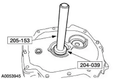
Installer, Bearing Cup 204-039 (T77F-1217-B) |
|
|
Adapter for 303-224 (Handle) 205-153 (T80T-4000-W) |
|
|
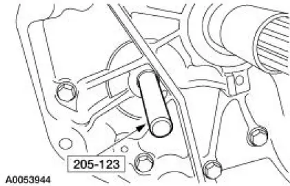
Installer, Axle Shaft Oil Seal 205-123 (T78P-1177-A) |
Material
| Item | Specification |
| DEXRON III (ATF) Transmission Fluid XT-2-QDX or equivalent | DEXRON III |
| Premium Long Life Grease XG-1-C, K or T | ESA-M1C75-B |
| Threadlock and Sealer E0AZ-19554-AA | WSK-M2G351-A5 (type II) |
| Black Non-Acid Cure Silicone Rubber E7TZ-19562-A | ESL-M4G273-A |
1. Lubricate all components with transmission fluid during assembly.
2. Attach the transmission adapter plate to the special tool.
3. NOTE: If a new front input shaft bearing or front countershaft bearing was installed, install new bearing cups.
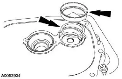
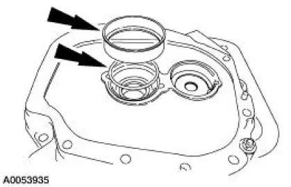
Install the input shaft bearing cup and the countershaft bearing cup. Do not install the shims at this time.
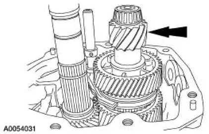
4. Install the input shaft.
5. Install the mainshaft onto the input shaft.
6. Install the countershaft.
- Lift the mainshaft upward, tilt the countershaft and install.
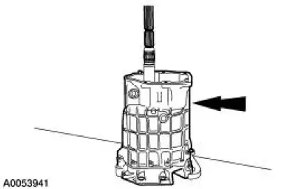
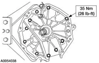
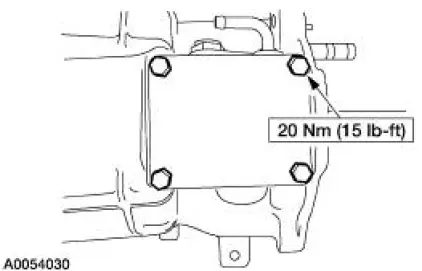
7. Install the transmission case and tighten the bolts.
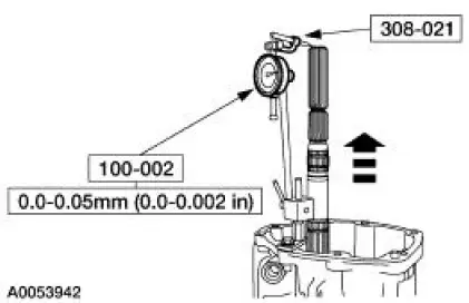
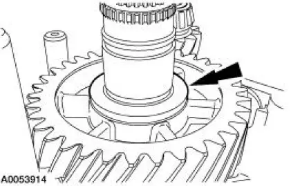
8. NOTE: Rotate the transmission so that the input shaft is pointing downward.
NOTE: Rotate the input shaft/mainshaft to seat the bearings.
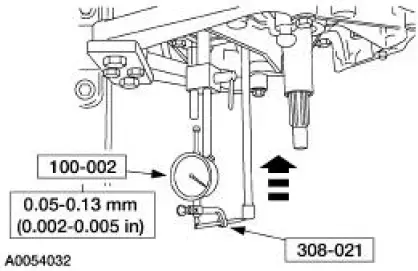
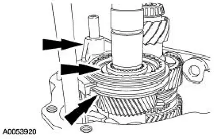
Using the special tools, measure the input shaft/mainshaft end play by applying an upward load on the input shaft. Record the measurement.
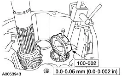
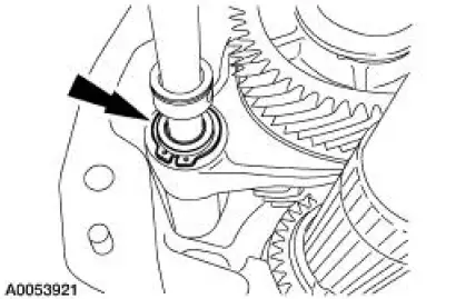
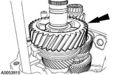
9. Reposition the special tool on the countershaft. Place the tip of the dial between the fingers on the countershaft.
10. NOTE: Rotate the countershaft to seat the bearings.
Using the special tools, measure the countershaft gear end play by pushing upward on the countershaft. Record the measurement.
- Unscrew the installer from the handle. Insert the handle into the adapter plate plug hole.
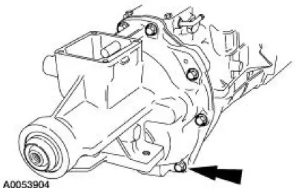
11. Remove the bolts and the transmission case.
12. Remove the countershaft.
13. Remove the mainshaft.
14. Remove the input shaft.
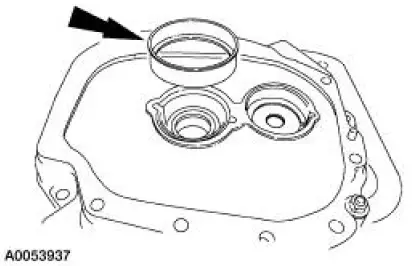
15. Remove the input shaft bearing cup and the countershaft bearing cup.
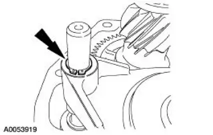
16. Using the special tools, install the new input shaft seal.
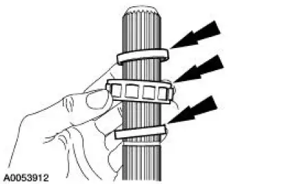
17. Using the recorded end play measurements, select and install the appropriate shims to achieve the proper end play. Install the front input shaft bearing cup and the front countershaft bearing cup.
- Lubricate the bearing cups with petroleum jelly.
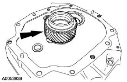
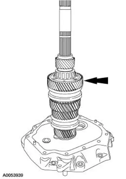
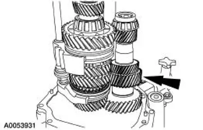
18. Install the input shaft and fourth gear synchronizer blocking ring.
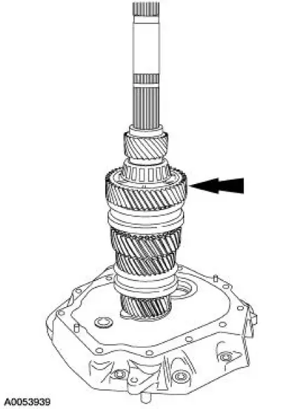
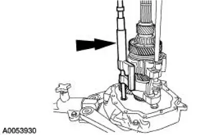
19. Assemble the shift rail assembly to the mainshaft, then install the mainshaft and shift rail as an assembly.
- Rotate the mainshaft to engage the fourth gear synchronizer blocking ring with the synchronizer keys.
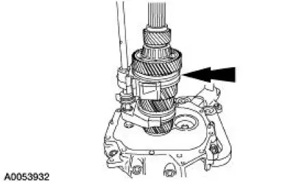
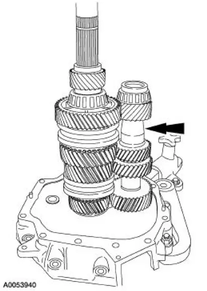
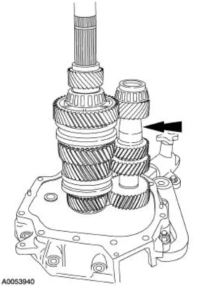
20. Lift up the mainshaft, then install the countershaft.
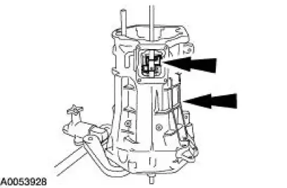
21. Install the fifth/sixth and reverse shift rail assembly and align the slots of the shift levers with the shift interlock plate.
22. Clean the mating surfaces of the transmission main case and the transmission adapter plate.
Apply a bead of silicone rubber to the sealing surface on the transmission adapter plate. Install the spring and detent ball into the front offset lever, then install the transmission case and the front offset lever.
- Make sure the transmission is in neutral to keep the third/fourth gear shift rail from engaging.
- Compress the front offset lever against the guide plate when installing.
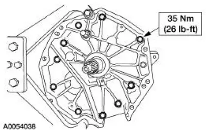
- Tighten the bolts in a star pattern.
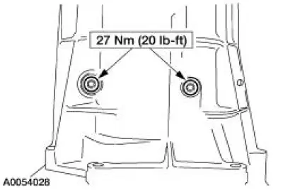
23. Apply threadlock and sealer to the threads of the shift lever guide bolts, then install the bolts.
- Pull up on the fifth/sixth shift rail to align the slot of the interlock plate with the guide bolt hole.
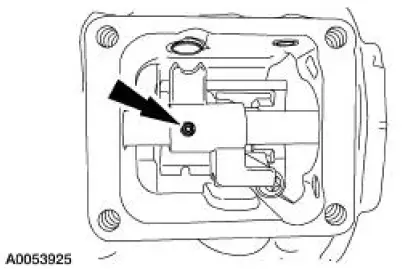
24. Install a new front offset lever roll pin.
- Install the pin until it is flush with the lever.
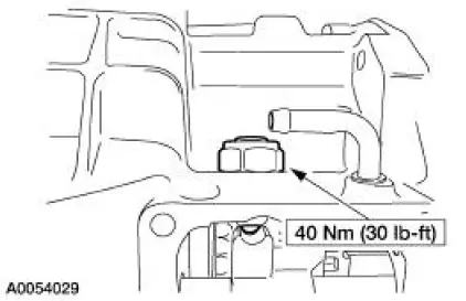
25. Apply threadlock and sealer to the threads of the shift dent, then install the shift detent assembly.
26. Clean the mating surfaces of the transmission main case and the shift detent cover. Apply a bead of silicone rubber to the sealing surface on the transmission case. Install the cover and tighten the bolts.
27. Rotate the transmission to a horizontal position. Install the countershaft extension assembly and the fifth/sixth gear shift fork. Make sure the splines are fully engaged.
28. NOTE: Remove the countershaft extension shim from the extension housing.
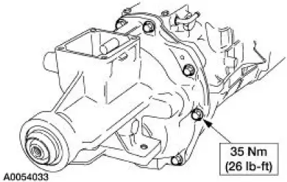
Install the extension housing and tighten the bolts.
29. NOTE: Rotate the transmission to the vertical position.
Using the special tools, measure the countershaft extension end play by pushing upward on the countershaft extension. Record the measurement.
- Insert a suitable bar into the adapter plate plug hole until it engages the countershaft extension.
30. Remove the extension housing.
31. NOTE: If a new countershaft extension bearing was installed, install a new bearing cup.
Using the recorded end play measurement, select and install the appropriate shims to achieve the proper end play. Install the countershaft extension bearing cup.
- Lubricate the bearing cup with petroleum jelly.
32. Install the fifth/sixth shift fork snap ring.
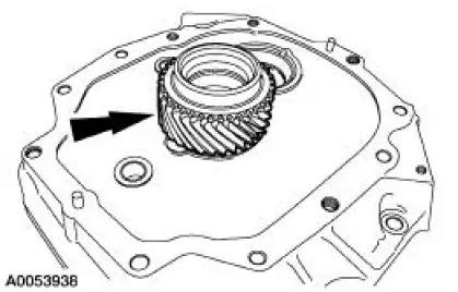
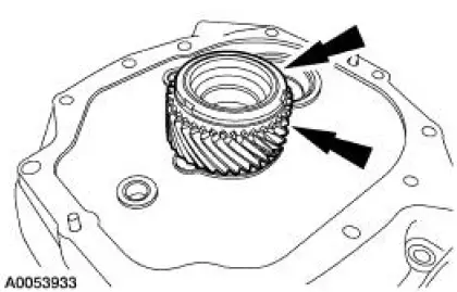
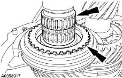
33. Using the special tool, press the fifth/sixth driven gear.
- Align the splines of the fifth/sixth driven gear with the drive gear on the countershaft extension.
34. Install the reverse shift fork, the reverse synchronizer and the thrust washer as an assembly.
- Align the pockets in the blocking ring with the struts in the synchronizer.
35. Install the reverse shift fork snap ring.
36. Install a new reverse gear synchronizer snap ring.
37. Install the reverse gear needle bearing and the reverse gear synchronizer blocking ring.
38. Install the reverse gear wave washer.
39. Install reverse gear.
40. Install the reverse gear thrust washer.
41. Install a new reverse gear snap ring.
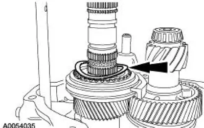
42. Install the lower spacer, the rear mainshaft roller bearing and the upper spacer.
43. Install the rear mainshaft roller bearing snap ring.
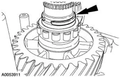
44. Install a new output speed shaft (OSS) sensor tone wheel lower retaining ring.
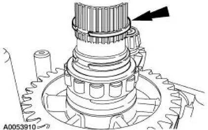
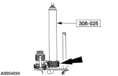
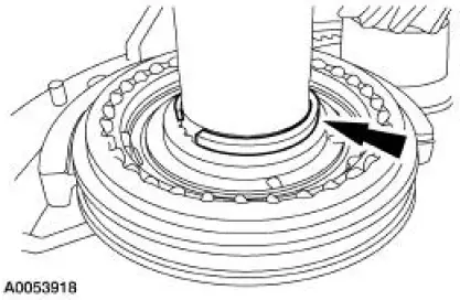
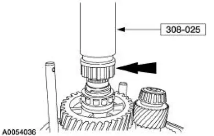
45. Using the special tool, install the OSS sensor tone wheel.
46. Install a new OSS sensor tone wheel retaining ring.
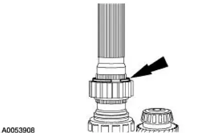
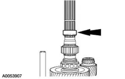
47. Install the shipping seal.
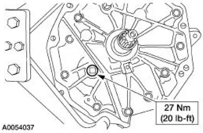
48. Apply threadlock and sealer to the threads of the plug, then install the plug into the transmission adapter plate.
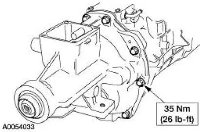
49. Clean the mating surfaces of the transmission main case and the extension housing. Apply a bead of silicone rubber to the sealing surface on the transmission case. Install the extension housing and tighten the bolts.
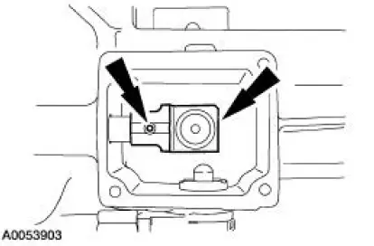
50. Install the rear offset shift lever, then install a new roll pin.
- Install the pin until it is flush with the lever.
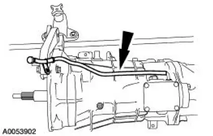
51. Install the vent hose.
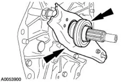
52. NOTE: Before installing the transmission, the ball stud, the clutch release lever and the input shaft guide tube must be cleaned and lubricated.
Install the clutch release lever and the clutch release hub and bearing.
 Transmission Case
Special Tool(s)
Handle
205-D055 (D81L-4000-A)
Installer, Bearing Cup
204-039 (T77F-1217-B)
Installer, Drive Pinion Bearing
Cup
205-054 (T71P-4616-A)
...
 Transmission (Installation)
Material
Item
Specification
DEXRON III (ATF)
Transmission Fluid
XT-2-QDX or equivalent
DEXRON III
Pipe Sealant with Teflon
D8AZ-19554-A or equivalent
WSK-M2G350-
A2
...
Other materials:
Pinpoint Test O: DTC B1870 - Air Bag Indicator Shorted to Battery
Normal Operation
The air bag indicator is designed to illuminate for 6 (+/-2) seconds
when the ignition switch is turned to
the RUN position. This initial 6 seconds of illumination is considered
normal operation and is called
proveout of the air ba ...
Spring Lock Couplings
Special Tool(s)
Disconnect Tool, Spring Lock
Coupling (3/8 inch yellow)
310-D004 (D87L-9280-A) or
equivalent
Disconnect Tool, Spring Lock
Coupling (1/2 inch green)
310-D005 (D87L-9280-B) or
equivalent
Material
Item
...
Symptom Chart
Condition
Possible Sources
Action
Hard Steering or
Lack of Assist
Seized lower steering
column shaft U-joints.
Damaged, fractured
steering column
bearing(s).
Power steering pump.
Suspension
components.
...
