Ford Mustang (1999-2004) Service Manual: Transmission Case
Special Tool(s)
|
|
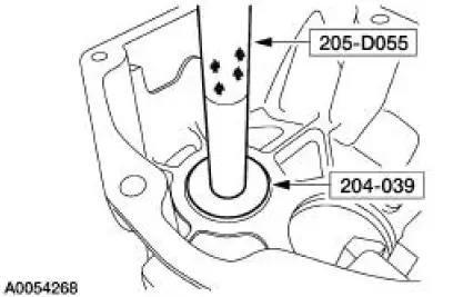
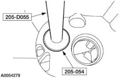
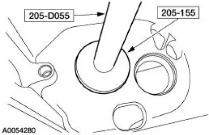
Handle 205-D055 (D81L-4000-A) |
|
|
Installer, Bearing Cup 204-039 (T77F-1217-B) |
|
|
Installer, Drive Pinion Bearing Cup 205-054 (T71P-4616-A) |
|
|
Installer, Rear Axle Oil Seal 205-155 (T80T-4000-Y) |
Disassembly and Assembly
1. Remove the bolts and the guide plate.
- Inspect the plate for wear or damage. Install a new plate as necessary.
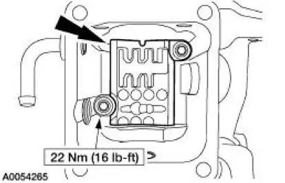
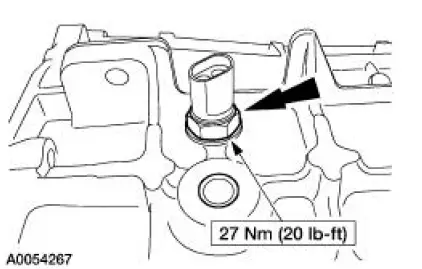
2. Remove the case magnets.
3. Remove the reverse lamp switch.
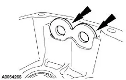
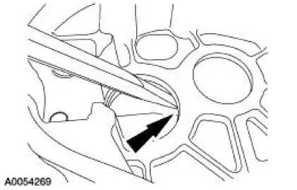
4. Using the special tools, remove the countershaft bearing cup.
5. Using a brass drift, remove mainshaft bearing cup.
6. Inspect the countershaft and mainshaft bearing cups for wear or damage. Install new components as necessary.
7. WARNING: Make sure protective eye wear is in place.
Clean the case with solvent and dry with compressed air. Clean and check the sealing surface for nicks or scratches. Inspect the case for cracks.
- If the case is cracked, install a new case. If the sealing surface has nicks or scratches, use a soft stone or crocus cloth to remove.
8. NOTE: If a new countershaft bearing is being installed, install a new bearing cup. Always install new bearings and cups in a set.
Using the special tools, install the countershaft bearing cup.
9. NOTE: If a new mainshaft bearing is being installed, install a new bearing cup. Always install new bearings and cups in a set.
Using the special tools, install the mainshaft bearing cup.
10. To assemble, reverse the disassembly procedure.
 Extension Housing
Special Tool(s)
Installer, Bearing Cup
204-039 (T77F-1217-B)
Adapter for 303-224 (Handle)
205-153 (T80T-4000-W)
Disassembly and Assembly
1. Remove the bolt and ...
 Transmission (Assembly)
Special Tool(s)
Dial Indicator Gauge with
Holding Fixture
100-002 (TOOL-4201-C) or
equivalent
Holding Fixture, Transmission
307-003 (T57L-500-B)
Remover/Inst ...
Other materials:
Air Conditioning (Description and Operation)
The A/C refrigerant system is a clutch cycling orifice tube type. The system
components are:
A/C compressor (19703)
A/C clutch (2884)
A/C condenser core (19712)
A/C evaporator core (19860)
suction accumulator (19C836)
connecting refrigerant lines
The ...
Inspection and Verification
WARNING: Use of any other than the approved DOT 3 brake fluid will
cause permanent
damage to brake components and will render the brakes inoperative.
WARNING: Brake fluid contains polyglycol ethers and polyglycols. Avoid contact
with
eyes. Wash hands thorou ...
Engine Front Cover
Material
Item
Specification
Metal Surface Cleaner
F4AZ-19A536-RA or equivalent
WSE-M5B392-
A
Silicone Gasket and Sealant
F7AZ-19554-EA or equivalent
WSE-M4G323-
A4
SAE 5W-30 Premium Synthetic
Blend Motor Oil
XO-5W30-QSP ...
