Ford Mustang (1999-2004) Service Manual: Assembly
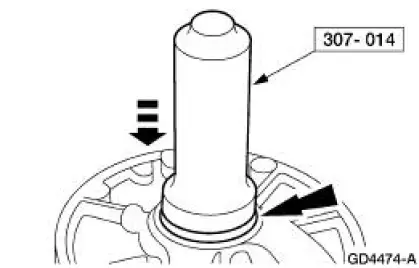
1. Using the special tool, install the front pump seal assembly.
2. Install the clutch piston seals.
1. Install the intermediate clutch piston outer seal.
2. Install the intermediate clutch piston inner seal.
3. NOTE: Coat the intermediate clutch piston outer seal, inner seal and pump body with petroleum jelly.
Install the intermediate clutch piston into the special tool.
4. Using the special tool, install the intermediate clutch piston.
1. Position the intermediate clutch piston and the special tool onto the pump body.
2. Push the intermediate clutch piston to the bottom of the pump body bore, exerting even pressure and remove the special tool.
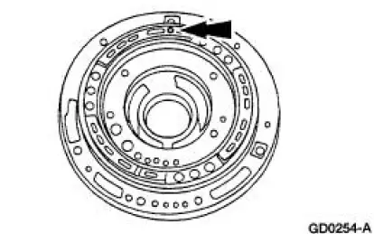
5. CAUTION: The piston bleed hole must be located at 12 o'clock position (towards the top of the transmission). Shift problems may occur if installed incorrectly.
NOTE: The piston bleed hole is the only round hole in the pump body.
Locate the piston bleed hole.
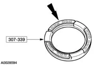
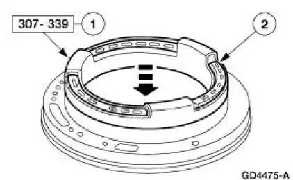
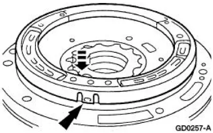
6. Install by snapping the spring retainer assembly on pump body.
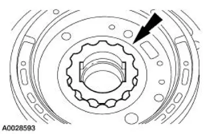
7. NOTE: The flats on the inner fluid pump gear have steps that must face the pump body or damage will result.
Install the inner and outer fluid pump gerotor gears.
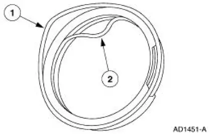
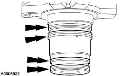
8. NOTE: The reverse clutch cylinder seal rings are larger than the forward clutch cylinder seals.
Install the seal rings.
9. Install a new front pump seal.
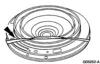
10. Assemble the front pump.
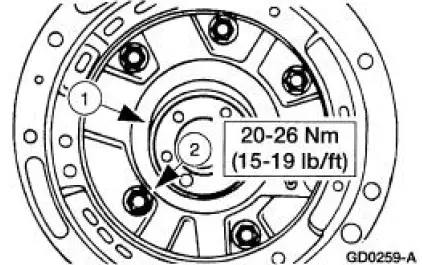
1. Position the pump support to the pump body assembly.
2. Install the bolts.
 Disassembly
1. Remove the No. 1 selective pump support thrust washer.
2. Remove the front pump support.
1. Remove the bolts.
2. Remove the front pump support.
3. Remove the seal rings.
4. Remove the in ...
 Intermediate One-Way Clutch
Intermediate Clutch Cylinder Disassembled View
Disassembly
1. NOTE: One tab that locks the reverse clutch drum into the reverse
sun shell may be removed.
This is done for balancing purpos ...
Other materials:
Horn (Diagnosis and Testing)
Refer to Wiring Diagrams Cell 44 , Horns/Cigar Lighter for schematic
and connector information.
Special Tool(s)
73 Digital Multimeter or
equivalent
105-R0051
Inspection and Verification
1. Verify the customer concern by operating the h ...
Fuel Charging And Controls
The fuel injection supply manifold (9F792):
delivers fuel to the fuel injector.
receives fuel from the fuel supply line.
The throttle body (9E926):
controls air supply to the upper intake manifold (9424) by positioning
the throttle plate.
connects the ...
Windshield wipers
Note: Fully defrost the windshield before switching on the windshield
wipers.
Note: Make sure you switch off the windshield wipers before entering a
car wash.
Note: Clean the windshield and wiper blades if they begin to leave
streaks or smears. If that does ...
