Ford Mustang (1999-2004) Service Manual: Assembly
1. Inspect the clutch cylinder thrust surfaces, piston bore and clutch plate serrations for scores or burrs. Minor scores or burrs may be removed with crocus cloth. Install a new clutch cylinder if badly scored or damaged.
2. Check the fluid passage in the clutch cylinder for obstructions. Clean out all fluid passages.
Inspect the clutch piston for scores and install a new piston if necessary. Inspect check balls for freedom of movement and correct seating.
3. Check the clutch release spring for distortion and cracks. Install a new spring (including the wave spring) if distorted or cracked.
4. Inspect composition clutch plates, steel clutch plates and clutch pressure plate for worn or scored bearing surfaces. Install new parts if they are deeply scored or burred.
5. Check the clutch plates for flatness and fit on the clutch hub serrations. Discard any plate that does not slide freely on serrations or that is not flat.
6. Check the clutch hub thrust surfaces for scores and the clutch hub splines for wear.
7. NOTE: To aid handling, the forward clutch assembly may be set in the extension housing or a hole in the work bench.
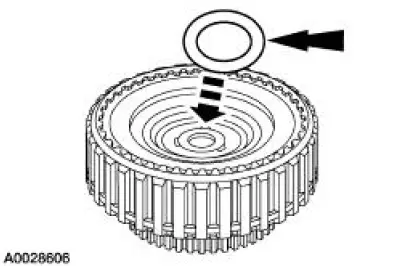
Install the inner and outer forward clutch piston seals. Note the direction of the sealing rings before installation.
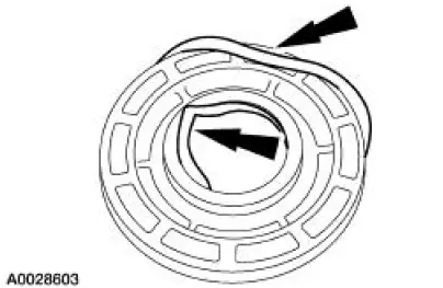
8. NOTE: Coat the piston seals and clutch drum sealing area with petroleum jelly.
Position the special tools on the clutch piston.
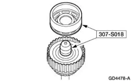
9. Using the special tools, install the forward clutch piston into the clutch drum.
- Push the piston to the bottom of the drum using even pressure.
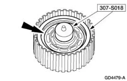
10. Using the special tool, compress the piston return spring and install the retaining ring.
11. Slowly release the press pressure and remove the forward clutch.
12. NOTE: Before assembly, soak the new clutch discs in clean automatic transmission fluid for 15 minutes.
Install the clutch pack assembly.
1. Install the pressure ring.
2. Install the clutch pack.
3. Install the pressure plate.
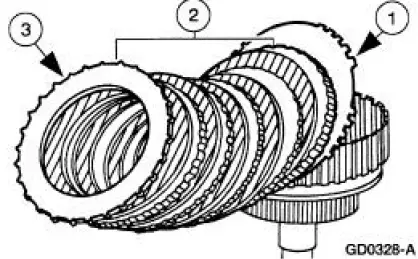
13. Install the clutch pack retaining ring.
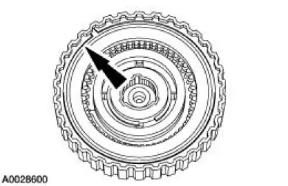
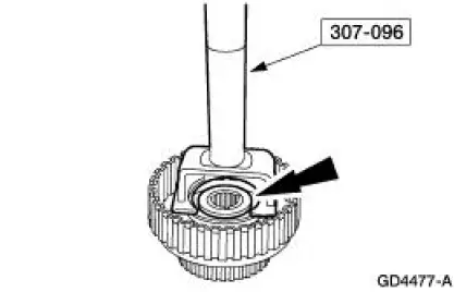
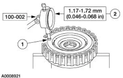
14. Install the special tool on the forward clutch pack.
- Push downward on the clutch pack.
- Release pressure and zero the dial indicator.
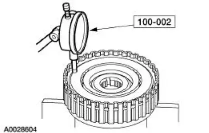
15. Using the special tool, check the clutch pack clearance.
1. Lift up on the clutch pack until it fully seats against the clutch pressure plate retainer.
2. Read the dial indicator.
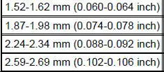
- If the clearance is not within specifications, install the correct size retaining ring.
Selective Retaining Ring
Specification
16. NOTE: Make sure the scarf-cut seals are mated correctly.
Slide the two scarf-cut seals on the input shaft.
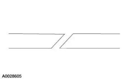
17. Install the two scarf-cut seals on the input shaft.
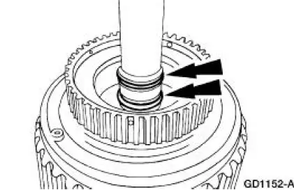
18. Install the No. 3 forward clutch hub front bearing and the forward clutch hub.
 Disassembly
1. Inspect the clutch cylinder thrust surfaces, piston bore and clutch plate
serrations for scores or
burrs. Minor scores or burrs may be removed with crocus cloth. Install a new
clutch cylinder if ...
 Planetary Gear Support Assembly and Planetary One-Way
Clutch
Planetary Gear Support Assembly and Planetary One-Way
Clutch
Disassembly and Assembly
1. NOTE: Inspect the outer and inner races for scores or damaged
surface areas where rollers
contact the races. Inspect the rollers and springs for excessive wear ...
Other materials:
Assembly
1. Install the valve stem seals.
2. Install the valves and the valve springs.
3. CAUTION: Make sure the tool is seated correctly on the valve spring.
Apply a small
amount of air at a time. This will prevent the tool from shifting and causing
damage to
the ...
Child seat positioning
WARNING: Airbags can kill or injure a child in a child seat.
Never place a rear-facing child seat in front of an active airbag.
If you must use a forward-facing child seat in the front seat, move the
vehicle seat upon which the child seat is installed all th ...
Removal
1. Disconnect the battery ground cable.
2. Remove the air cleaner outlet pipe.
3. Remove the radiator sight shield.
4. Remove the coolant recovery reservoir.
1. Disconnect the hose.
2. Remove the bolts.
3. Remove the coolant recovery reservoir ...
